Well I've finally been able to get things together in order to start a build thread on my custom tube amp as requested by a few others. I first posted about it here:
http://www.talkbass.com/forum/showthread.php?t=710734
Scott (our guitarist, aka RoctalAmps) is building the amp so any technical details will have to be answered by him.
Here are a few details about the build and what we're shooting for.
-Tube compliment: 6sj7, 6sl7, 6sn7, in the pre-amp
-Traynor style tone stack with mid-shift and parallel/serial mixing effects loop.
-EL34 driver stage through an Fender PS-400 interstage transformer, with clipping feature to get the 'svt' cranked sound in the driver stage
-4CX250B RF tetrode in the output stage running around 900 volts on the plates.
-Antek toroid power transformer
-300-watt Heyboer output transformer with home audio bandwidth of 20hz to 20khz
-2/4/8 ohm taps
-Shooting for 200 to 250 watts, possibly more.
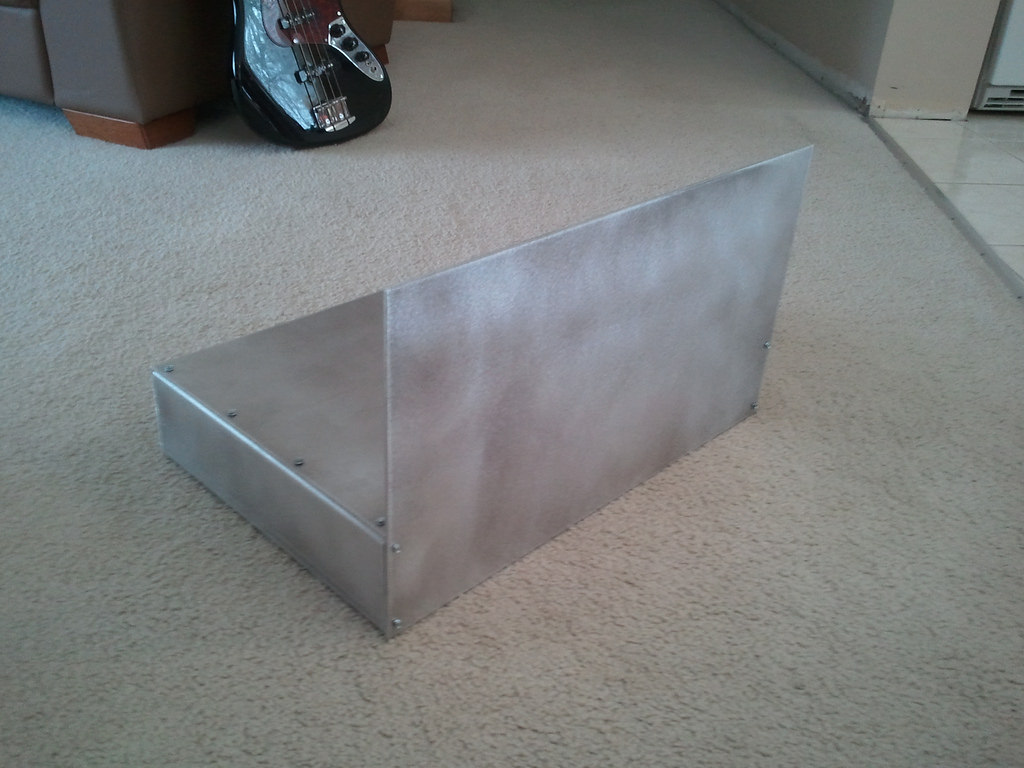
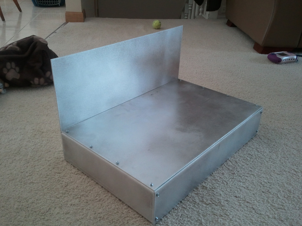
Here are a few shots of the chassis:
And a quick shot of a partial mock up:
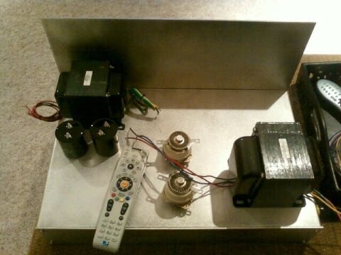
The big transformer the right is the output transformer, power transformer on the left. Ceramic RF tube are in the middle with a pair of 600v capacitors flanking them. The tubes run off of 1000v supply.
I'll try to answer any questions that I can. Otherwise I'll direct them to Scott.
I can't wait to try this thing out!
http://www.talkbass.com/forum/showthread.php?t=710734
Scott (our guitarist, aka RoctalAmps) is building the amp so any technical details will have to be answered by him.
Here are a few details about the build and what we're shooting for.
-Tube compliment: 6sj7, 6sl7, 6sn7, in the pre-amp
-Traynor style tone stack with mid-shift and parallel/serial mixing effects loop.
-EL34 driver stage through an Fender PS-400 interstage transformer, with clipping feature to get the 'svt' cranked sound in the driver stage
-4CX250B RF tetrode in the output stage running around 900 volts on the plates.
-Antek toroid power transformer
-300-watt Heyboer output transformer with home audio bandwidth of 20hz to 20khz
-2/4/8 ohm taps
-Shooting for 200 to 250 watts, possibly more.
Here are a few shots of the chassis:
And a quick shot of a partial mock up:
The big transformer the right is the output transformer, power transformer on the left. Ceramic RF tube are in the middle with a pair of 600v capacitors flanking them. The tubes run off of 1000v supply.
I'll try to answer any questions that I can. Otherwise I'll direct them to Scott.
I can't wait to try this thing out!