• TalkBass has been independent since 1998. Add your voice.
    Create a free account to reply to discussions, view embedded media, and browse with fewer display ads.
    Join freeLog in
    Want zero display ads or expanded classifieds tools? Compare plans.

Ampeg B25 (1969) repair to power switch

I recently acquired a non-working 1969 Ampeg B25. No owner to ask questions.

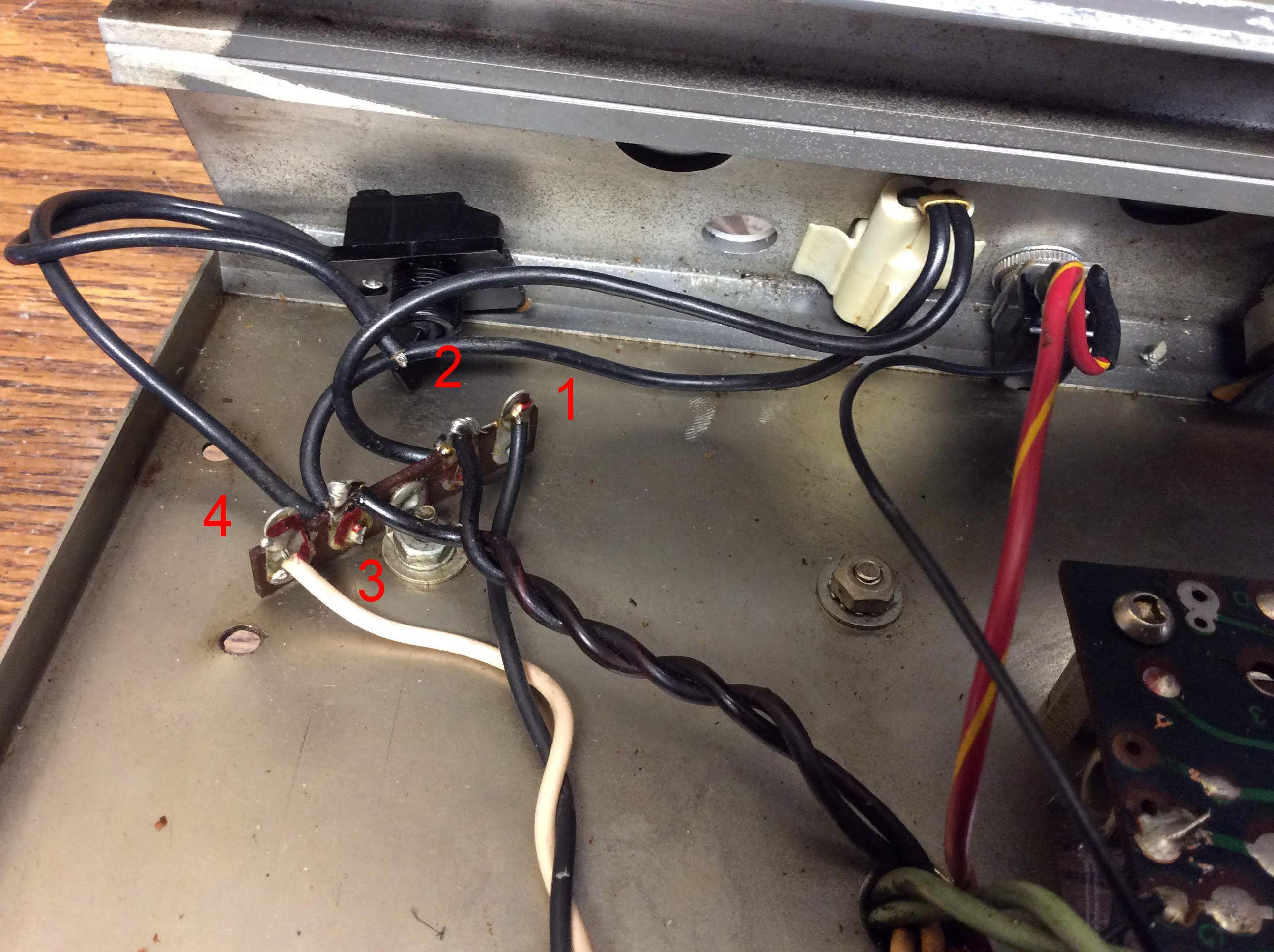
One lead to the power switch is has been cut off. I am trying to figure out where the other end should be soldered? See picture. The power cord has been replace with a 3 prong.

The fuse wire is soldered to terminal 1. There is a jumper between 1 and 2. The power indicator light is connected to 2 and 3 and the white wire is connected to 4 with nothing else connected to terminal 4. There are 3 wires on 2 and 3 that go a hole in the chassis to the transformer.

One lead of the power switch is connected to terminal 3. Where should I solder the other lead? I have a basic understanding of electronics and have the schematic. It seems like it should be soldered to terminal 4, but a power switch on the ground side does not make sense.
B25powerinput.jpg
 
If the switch is a simple toggle with a 1/2” mounting bushing, buy a new two pole single throw switch with a metal bushing and toggle. Mount it into the hole in the chassis. The switch will have four terminals.

The Black and white twisted pair I assume is coming from the new power cable. The black twisted pair is going to the power transformer. Is this correct? If it is let me know and we can proceed.
 
Paul,
1) Yes it is a simple single throw.
2) Yes, black and white twisted are coming from the power cord. Black via the fuse.
3) Yes, black twisted pair are going to the transformer.

I have a DPST switch for testing. I can buy a matching one later.

Thanks
 
Mount the switch. You will have a pair of terminals towards the top and another pair towards the bottom. On the terminal strip you should find a link between 3 and 4. cut it out. Terminal 4 will now only have the white wire. If you have a short length of white wire hanging about wire it from terminal 4 to the switch bottom left terminal. Another length of white wire connect from terminal 3 to the switch upper left terminal. The black wire that went from terminal 3 to the old switch is removed. This completes the neutral wiring.

If there is a link between terminal 1 and 2 it should be removed. Terminal 1 should only have one wire attached. Using the black wire you just recovered, wire terminal 1 to the switch bottom right terminal. With another length of black wire, connect terminal 2 to the switch upper right terminal.

What you have done is isolate the amplifier wiring from the AC supply with the power switch off.

If you want to go a step further buy a pair of 10n 1KV ceramic capacitors and wire one across terminals 1 and 2 and the other across terminals 3 and 4. These will act to quench any turn on arcs across the switch contacts.

I’m hoping that you have the skills to follow these instructions otherwise get a tech to do the work. :)

Please post a photo of the completed work for checking.
 
I understand what you are saying, and I have that skill set. Basically you are switching both power and ground.
The potential problem is Ampeg did not provide a lot of room for a switch. My current DPST switch which has solder lugs above and below will not fit. I will have to take some measurements and see what I can find with lugs coming out the back of the switch that will fit in that space. I will order capacitors at the same time.

I will post pics back if I can find a switch to fit.

In the mean time I did rewire in a SPST switch to the power side, and the amp came to life, so I know there is nothing seriously wrong.
 
I cannot find a DPST switch that will fit into the small space. The best I can do is a SPST, so I will wire that to the power side as discussed and leave the neutral as is. This is the switch I found that would fit. As you can see there is not much space (<1/4") below the bushing.
switch.jpg


I did get the capacitor. Any value in soldering it to the power side?

Bob
 
Arc quenching cap should be X or X2 rated for across the line applications.

For clarification, NEVER switch the ground, it must remain intact to the chassis at all times for safety purposes.
 
  • Like
Reactions: BassmanPaul
@beans-on-toast, those switches are the only switches I could find that would fit.

Thanks everyone for you guidance.

Here is the final restore. Replacing the Tolex was the most challenging, since I had never done it before.

View attachment 3388414

You did a very good job. Pat yourself on the back.

That knee on the front left and right front of the head case isn’t easy to do well. Proper wood prep, having that knee line right is the key.

