• TalkBass has been independent since 1998. Add your voice.
    Create a free account to reply to discussions, view embedded media, and browse with fewer display ads.
    Join freeLog in
    Want zero display ads or expanded classifieds tools? Compare plans.

Ampeg V4BH Problem

Hello everyone!

I have a problem with my Ampeg V4BH. Two of the power tube filaments doesn't light up sporadic. Sometimes I can play for over an hour on rehearsals without any problem at all several times. But the next time I power the amp up the two power tubes to the left (seen from the front) doesn't light up. All the other tubes including preamp and driver tubes light up as they should. Does anyone have a clue?

Regards, Ola
 

Attachments

  • C45C608A-9780-41E8-AD2F-2CC6A0160659.jpeg
    C45C608A-9780-41E8-AD2F-2CC6A0160659.jpeg
    229.9 KB · Views: 180
The same two tubes stop glowing. I put in brand new tubes yesterday. Worked fine, same brightness on all filaments with light blue color inside the bulbs. Today when I fired it up the two didn't glow.
 
If I understand the symptoms right - and I am not confident on that- If this has happened with two different sets of tubes (old ones and new ones) then it has got to be one of two things:
1) The filament chain has a bad connection somewhere, or
2) The tube sockets are not tensioned right or dirty and loosing contact.

Either the tubes get power or not. There is not a separate power source for tubes 1,2,3,4. If it is intermittent, then this screams a bad connection (or bad tubes, but it sounds like you check the tubes)
 
  • Like
Reactions: Wasnex
Bias and heaters are different circuits. I believe this amp provides 6.3V AC to the output tubes and rectifies the AC to DC for some or all of the small signal tubes. Based on the way the schematics are labeled, the DC may only be used by V1 in the preamp.

The schematic shows bias at approximately -45V DC.

The tubes do not require bias or high voltage for the heaters to light.

If the heaters are intermittent, it could be the tubes, or it could be an intermittent connection to include loose pins on the tube sockets. If you do not have any electronics background, the best course of action is to take the amp to a qualified tech. This is for your safety and the amp's safety.

If you are going to poke around in the amp, you need to know there are potentially lethal voltages present, so you need to be careful.

Remove jewelry and only use one hand. The reason to use only one hand is to prevent any potential shock from travel through your heart. Young techs are taught to hold the unused hand behind there back.

Check the pins on the tube sockets for heater voltage. For the 6L6 tubes the heater pins are 7 and 2.
upload_2022-6-14_16-53-53.png


For the small signal tubes the heater pins are 4 to 9 for the A side of the tube and 5 to 9 for the B side of the tube.
upload_2022-6-14_16-47-16.png


You may need to tighten up the pins in the tube sockets. This is done with a tool that looks like a dental pick. Before attempting this procedure, the power supply capacitors must be discharged, as they can hold high voltage DC after the amp is turned off.

I don't consider it ideal to simply short the capacitors. I real tech would have some sort of jig to bleed away the charge. I use some insulate test leads with a fairly large resistor. One end of the test lead is clipped to the chassis, and the other holds the resistor. The resistor is touched to all of the capacitor terminals and slows the rate of discharge. check the capacitors with a multi-meter rather than assuming the procedure worked.

[Invalid or Expired Link Removed]
 
According to the schematic and the physical board it seems that the power tubes gets feeded in pairs. Look at the picture I posted now with the power tube board removed. There is J10 and J11 connectors.
 

Attachments

  • B2ED7D7B-8706-434F-A72E-53D800DABA9A.jpeg
    B2ED7D7B-8706-434F-A72E-53D800DABA9A.jpeg
    1.3 MB · Views: 184
Hello everyone!

I have a problem with my Ampeg V4BH. Two of the power tube filaments doesn't light up sporadic. Sometimes I can play for over an hour on rehearsals without any problem at all several times. But the next time I power the amp up the two power tubes to the left (seen from the front) doesn't light up. All the other tubes including preamp and driver tubes light up as they should. Does anyone have a clue?

Regards, Ola
New or used? If new, send it back for another. Used, follow carefully @Wasnex advices and check your heater voltages afterward.
 
  • Like
Reactions: Wasnex
According to the schematic and the physical board it seems that the power tubes gets feeded in pairs. Look at the picture I posted now with the power tube board removed. There is J10 and J11 connectors.

Aggressive :eek:!

Yes the tubes are fed in pairs from H1 and H2. The yellow transformer leads are the heater taps. One is connected to J43 which feeds H1. The other is connected to J41 which feeds the heater fuse (F6). F6 feeds H2. There is also a green lead (center tap) connected to J42.

What do you plan to do next?
 
  • Like
Reactions: Patrice B
you are loosing heater power to those 2 tubes ! , as said before BE CAREFUL tube amps can kill . no BS !!!
Because there are circuit boards it can be a bad trace also with the caps shorted use a volt meter to check continuity from the heayter wires to the tube sockets , It sounds like it is intermittent which is a worst case to trouble shoot you may need to tap the board with a meter attached to locate the broken section.
 
EGADS! An integrated PCB board that connects to tube sockets? What evil trickery is this?!?

I am out. Over my mere analogue abilities, hand-wired abilities....

Seriously, I am sorry, I don't know that layout.
Absolutely no problem with properly designed PCB mounted tube sockets if you know how to work on amps and have the necessary skill set. In fact, I generally find them more reliable.
 
If the tube sockets are soldered to the PCB, make sure there are no cracked/broken solder joints on the solder side of the PCB where the sockets are soldered to it. Also, if there are in line connectors (common on many amps with PCBs) bringing the filament voltage from the power supply to the PCB where the output tube sockets are, check to make sure that there are no cracked/broken solder joints under those connectors as well. Also I have seen where the actual connectors fail (the pin/socket) because of heat. There is a fair amount of current passing through those connectors and with heat, the spring tension on the female side of the connector will tend to loosen up causing higher heat which in turn will cause higher resistance in the pin contacts which in turn causes more heat....it becomes a vicious cycle. The connection will eventually fail.

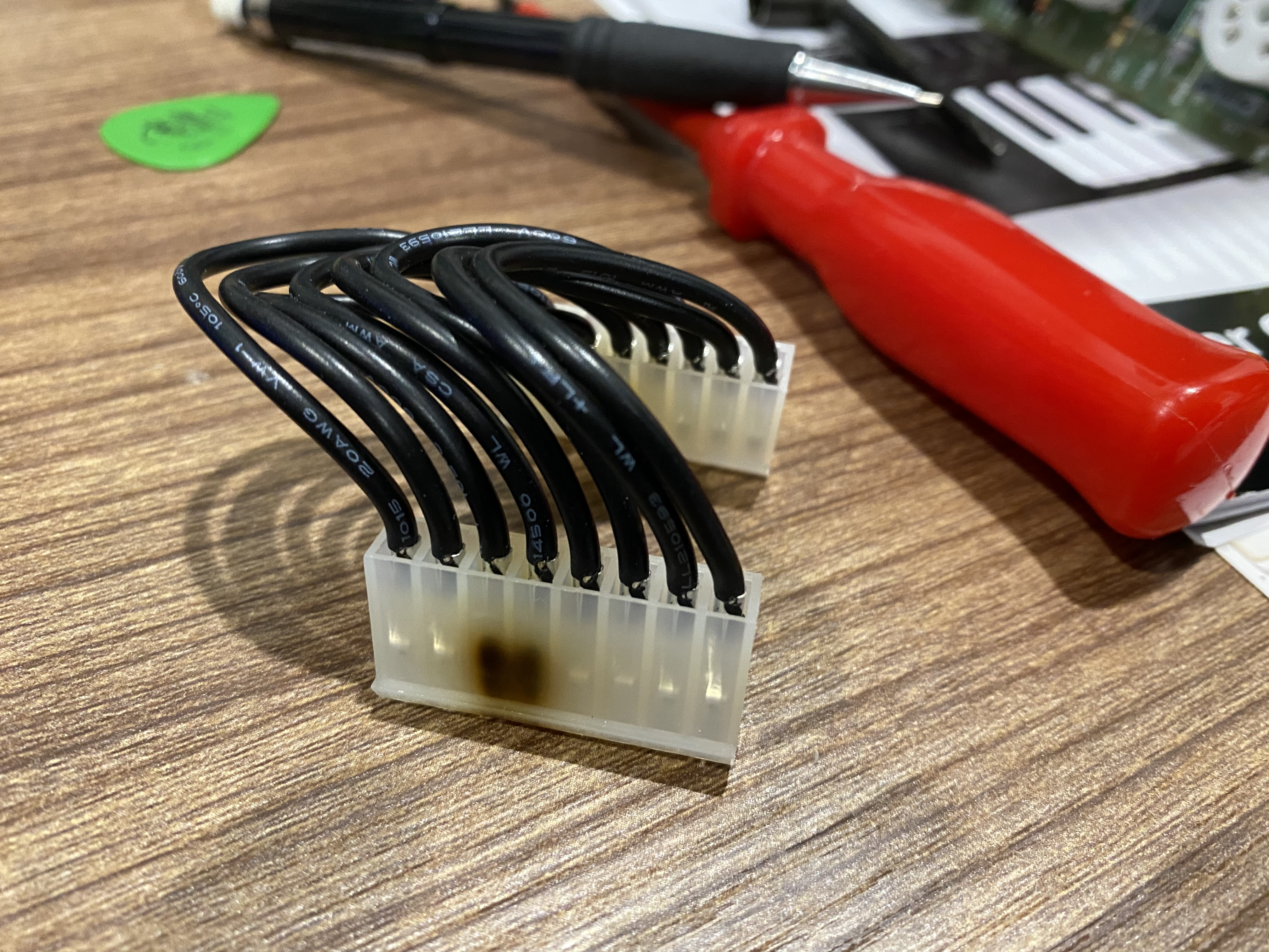
Here's what a failed connector looks like because of resistance in the connection causing hot pins:

IMG-1158.jpg
 
Last edited:
If I sum up all of your answers it seems that it most likely is a bad connection in the inline connector either female or male. What is strange is that everytime the problem has occurred the unit has been cold. Only one time the two tubes has died during use.
 
  • Like
Reactions: Wasnex
If I sum up all of your answers it seems that it most likely is a bad connection in the inline connector either female or male. What is strange is that everytime the problem has occurred the unit has been cold. Only one time the two tubes has died during use.


Since it's the heaters in two tubes going out, and the tubes are organized in pairs on the output tube board, take a look at the connectors associated with the dead tubes. So if V3 and V4, it's mostly like J205 and J10. If V5 and V6, it's most likely J206 and J11.

Inspect the connectors for thermal damage and carbon build up.

I believe these are the approximate paths the heater voltage takes from the transformer heater tap connections at J43 and J41 to the pins on J10 and J11.
upload_2022-6-15_2-48-16.png

I think the traces are good on this board. The traces continue to the left and then loop down and back to the right to the two small signal tubes on this board. The image you posted shows the heaters in the two small signal tubes are lit.


I believe this is how the output tube board is oriented over this preceding image:
upload_2022-6-15_3-51-6.png


I added the approximate paths of the heater traces to the bottom copy of the image. Note the green path goes to pin 6 on two tubes. Pin 6 is not terminated inside the tube. Pins 2 and 7 are the heaters connections.


Base on the image you posted, the two tubes with dead heaters would be on the left in this image. That should make them V5 and V6.
 
Thank God for your superb knowledge.

I have ordered 13-pin connectors both female and male that I'm gonna solder in when they arrive. When I looked closer into the picture of the board I noticed that pin 4-6 looking burned. I have zoomed in on the picture here.