• TalkBass has been independent since 1998. Add your voice.
    Create a free account to reply to discussions, view embedded media, and browse with fewer display ads.
    Join freeLog in
    Want zero display ads or expanded classifieds tools? Compare plans.

Double Bass Barn Bass Project

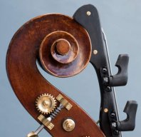
Well yeah! The pegbox cheeks are angled so when the tuner is mounted square to the box the capstan shaft will be at an angle to the centre line of the instrument.

I think the angle is helpful in terms of keeping the string windings squeezed together up against the hole in the shaft... ;)

That's true, I didn't think of that.

I just wondered which of the 2 were the main reason for angled shafts - ease of drilling the angled cheeks, or the specific purpose of keeping windings tight against the hole (as each turn of the key moves up the string up the shaft).

I hope this paragraph doesn't sound too dirty.

George
 
I suspect they were jammed or stiff, or the owner couldn't get the strings to wind on evenly :rolleyes:

So the genius in the family said "that's because they're not on straight, if they were, there would be more efficient transfer of force, and less possibility of wear to the parts over time"

and got to work!

in keeping with that line of thought...said genius should have mounted the thumbscrews up... he/she could have tuned with their right hand. ;)
 
This old "flat"back was a sorry sight. The maple plates had dried out and strained against the horizontal bracing and made a Pringle-looking thing, at least 1" concaved. When I freed the maple from the bracing and steamed it a little it flatten out pretty good though. The seam was open and there was a stress crack that I am cutting out with a insert that will also fix a button problem as well as a width problem.

Now, seems to me the flat-back design is a ticking time bomb of questionable design. We have here vertical grain plates that swell and shrink in width with moisture variation that are hard-glued to spruce horizontal with-grain bracing that for the most part doesn't. Something is bound to give if the humidity changes.

Are there any builder's tricks to ease the stressful situation?

The only thing I can come up with is using an elastomeric glue rather than hide. Any thoughts (except only hide is kosher)?

Thanks.
 
After looking at your pics, a few thoughts ...

1. make sure the wood is very dry before gluing! But I think you have this problem sorted by now ...
2. shape the braces to put a slight convex dome in the flat back.
3. narrower upper and lower braces (less glue surface)
4. keep the braces clear of the linings
5. taper the braces at the edges to allow them to flex but still support in the middle

The upper and lower braces on a Lott Sr flatback I had on the bench recently were about 1cm wide and 1.5cm tall. My initial reaction was that they looked undersized ... but who knows?
 
Now, seems to me the flat-back design is a ticking time bomb of questionable design. We have here vertical grain plates that swell and shrink in width with moisture variation that are hard-glued to spruce horizontal with-grain bracing that for the most part doesn't. Something is bound to give if the humidity changes.

Are there any builder's tricks to ease the stressful situation?

Don't know if you've seen this link pertaining to a diagonal back-brace design. There's a link to a pic in the thread somewhere.

http://www.talkbass.com/forum/f3/diagonal-back-brace-upright-bass-716237/

Looks interesting, and I'd be interested to hear more from luthiers about the advantages/disadvantages of this kind of bracing.
 
After looking at your pics, a few thoughts ...

1. make sure the wood is very dry before gluing! But I think you have this problem sorted by now ...
2. shape the braces to put a slight convex dome in the flat back.
3. narrower upper and lower braces (less glue surface)
4. keep the braces clear of the linings
5. taper the braces at the edges to allow them to flex but still support in the middle

The upper and lower braces on a Lott Sr flatback I had on the bench recently were about 1cm wide and 1.5cm tall. My initial reaction was that they looked undersized ... but who knows?


Good insight, thanks Matthew.
 
Mike,

I really like the diagonal main brace design. It puts the grain about 75% in the right direction so it would reduce the shrinkage stress by 75%. It seems so logicial it makes one wonder why it is not common practice.
Thanks for the link.


Forester,

Yea, you are right. I am sure the hey-loft drying contributed greatly to the potato chip shape and it is an exaggeration of what normally happens when panels shrink if glued to a stick (furniture speak for cross-grain end piece).

As you know, in furniture building, panels are never hard-glued to a cross stick, they float in a groove or have a slip fit of some kind or another. But we can't have a loose panel flapping around in a slip-fit slotted brace in an instrument can we?

I am going to allow the maple back to acclimate with the bracing at least a month in storage before I glue them. Since it is winter and RH is < 40% the plates will still swell in summer humidity so I would expect some convexing anyway.
Thanks.
 
I don't know. In theory it would free the back to vibrate in sympathy with the top without the constraint of the sound post pushing into it. A flat back could be very lightly braced.

Guitar luthiers experiment a lot with internal bracing because I think the instruments are quicker to make and less expensive overall. So they CAN. True they don't have a soundpost to consider. But if the mantra is to build as light as you can without it all pulling apart, then I think there is probably still some way to go with experimenting with double bass bracing. It's not such an issue with violin or cello because the instruments are lighter and smaller anyway.
 
I have wondered what would happen if the sound post rested on a stiff floating brace anchored at the edges of the back plate only or into the ribs/corners. I guess I'll have to try it one day. Oh for another life.

Yea. I have considered an L-strut or U-beam shape where the SP platform was the lower part of the L or U and the sides were thin panels. It would bridge the forces of the back end of the SP to the ribs efficiently. The panels could be tapered and drilled for lightless.

I never tried the idea because I have come to the opinion that the SP actually puts the back in motion out of phase with the front (both move either in or out at the same time) and causes free-body radiation of sound. I know this is a over-simplification and I could be mistaken.


But I do want to run this up the flagpole -

I have an idea for the cross brace where the back bends. It would be about 1" w x 1.5" h in cross section and would be slotted like corner kerfing at about 1/2" o.c. and about 1/2" deep on the plate side (with the angle). This would allow for good control of the angle planes - the angle is fixed. The 1" unslotted section would provided support to the panel but the slots would allow 1/8" clearance for humidity shrink/swell of the panel between the glued faces. The structure may arch some (it could be preloaded) but the panel won't break or separate. Might work for about any cross brace on a panel actually. ????
 
Here is a forensics problem:

Invalid Link Removed


Someone took a lot of time and trouble to remount the origional machines perpendicular to the strings rather than at the slight angle the tapered peg box provided. It required shims under one edge of the machine plate and changed where the peg hit the other side, it missed the hole. So the holes were elongated (beavered out) and little wooden quarter-moon-shaped inserts were used to fill the space vacated.

Maybe the owner was a wheelwright and though all axles should be straight with the wagon but I can think of no good reason for such an enterprise, can you?

This photo is my new desktop background!

:hyper:
 
it would surprise me if the "quarter moons" were installed as that. More likely the previous holes were plugged with a dowel, then redrilled, leaving the quarter moon. But also likely one of them popped out later at some point, and was tacked back in by an amateur!

Quality varies with the repair. The peg box alteration where the pegs were all reset, was a mixture; some back porch where the quarter moons and the box were carved and some were drilled, plugged, and re-drilled. The carved (and the nail) may have been a later patch to the drilled as you said. I'll give someone credit for driving a 2p nail in the peg box cheek without splitting it though; maybe he drilled it first. Internal repairs, tagged 1948, were pretty well done, probably by a violin maker although there was paneling (plywood) used as seam patches.

The original bass is a interesting contrast in workmanship too. The neck and scroll are very nice but the final assembly such as the linings and corners were poorly fitted. The fingerboard, maybe a replacement, was painted maple with a knot in it.

Say Matthew or anyone, what is the best order of assembly?

I have the five major pieces nearly ready. I was thinking:

1. Black color on finger board (this stuff is all business) the FB is probably white oak
2. Glue back to ribs - fit the button install last back brace at angle
3. Check the neck angle and alignment with neck and top set in place
4. Glue FB to neck
5. Glue neck in block
6. Glue front to ribs
7. Finish back, touch up other areas
7. Apply trim
8. Finish plane neck as required and re-black.

Thanks.