
• TalkBass has been independent since 1998. Add your voice.
    Create a free account to reply to discussions, view embedded media, and browse with fewer display ads.
    Join freeLog in
    Want zero display ads or expanded classifieds tools? Compare plans.

Does this schematic approximate volume control?

On the last point - I didn't bring this up to see if I could improve it or anything like that. I'm interested in how the components affect the output just to better understand how/why the output of my bass changes as I fiddle with the knobs. I just started playing bass again after 20+ years without one (played a little back in high school). I'm finding that I'm a bit overwhelmed by all the knobs on my bass and amp. Seems like I endlessly cycle through various settings on knobs trying to find satisfying sounds. Probably need to start taking notes. But anyway, I think if I better understand how they work, the settings will start to make more sense. I think the way the EQ knobs and Gain/Volume are clear enough. Still having a little trouble understanding the notch filter, and then the interaction of the 3 knobs on my bass need some clarification in my mind. This discussion has helped with that.

To further enhance/confuse your understanding, the pots in your bass are most likely logarithmic taper, not linear taper. Turning a volume down from 10 to 9 will have a larger volume drop than from 9 to 8, etc.

And, the Tone knob is a basic low pass filter, not a notch filter. As you decrease the resistance on the tone pot, more and more highs are filtered to ground, leaving only the bass frequencies at the output.
 
  • Like
Reactions: skycruiser
To further enhance/confuse your understanding, the pots in your bass are most likely logarithmic taper, not linear taper. Turning a volume down from 10 to 9 will have a larger volume drop than from 9 to 8, etc.

And, the Tone knob is a basic low pass filter, not a notch filter. As you decrease the resistance on the tone pot, more and more highs are filtered to ground, leaving only the bass frequencies at the output.

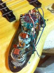
Thanks. I get more or less how the tone control works. Reducing the resistance to the capacitor (basically a low-pass filter) increases the amount of filtering, or maybe more accurately reduces the cut-off frequency of the filter, passing only the lows with minimum resistance as you said. I'm aware of the different pot tapers and basically get that you can us log/audio taper because the effect you are going for doesn't necessarily have a linear response - e.g. we don't perceive volume levels linearly.

If you’ve ever played a PJ before, or any two-pickup bass for that matter, you would know that the signal from each pickup are not perfectly in phase. Since each pickup senses a different portion of the string along its length, there is comb filtering that happens when the two signals are summed. This is what gives a Jazz bass it’s signature scooped sound with both pickups full on.

This is interesting info. I thought the main reason for the different positions was to pick up different harmonics in the string vibrations. Good to know there is also a phase effect that affects the resulting sound. This could be seen clearly by viewing both pickup outputs on an oscilloscope (before summing/averaging obviously).
 
  • Like
Reactions: NKBassman
Does anyone know if this is more or less correct?

Yes, I do know, and I'd say that your understanding is on the "less correct" side of things. You know a few things about the resistances you can measure with an ohmmeter, but that's not even the tip of the iceberg in terms of what's happening here.

You have ignored the inductance of the pickups (and some parasitic capacitances as well). You have ignored the capacitance of the cable. You haven't done anything wrong, but trying to do analysis with only what you know at present won't get you anywhere productive.

At 100Hz and below (your open g string is tuned about there), you can take the resistances of the pickups and pots, and what you get for an answer will be kinda OK. If you want to talk about overtones, or the transient when you pluck a note with your finger or a pick (some of the things that make any one bass sound different from another), you need to understand what's happening further up in the frequency range. A P bass has a much more 'textbook" volume control scheme - you run the volume pot down to where there's half of the resistance above and below the wiper on the pot, you're at half volume, and the tone hasn't changed much. A J or a PJ with a VVT circuit is far less simple (the volume pots are wired "backwards", and far less ideal - it's shunting the pickups' outputs, which has major implications on tone, but that isn't obvious until you understand the reactive elements in the circuit. Try turning down the volumes (both of them) to half on PJ, and do the same on a straight up P. Why do they work so different? Why can you run a P bass with the volume at half, but people don't ever run a Jazz bass with both volumes at half? The answers to these (and other questions) come from understanding the reactive impedances involved.
 
Yes, I do know, and I'd say that your understanding is on the "less correct" side of things. You know a few things about the resistances you can measure with an ohmmeter, but that's not even the tip of the iceberg in terms of what's happening here.

You have ignored the inductance of the pickups (and some parasitic capacitances as well). You have ignored the capacitance of the cable. You haven't done anything wrong, but trying to do analysis with only what you know at present won't get you anywhere productive.

At 100Hz and below (your open g string is tuned about there), you can take the resistances of the pickups and pots, and what you get for an answer will be kinda OK. If you want to talk about overtones, or the transient when you pluck a note with your finger or a pick (some of the things that make any one bass sound different from another), you need to understand what's happening further up in the frequency range. A P bass has a much more 'textbook" volume control scheme - you run the volume pot down to where there's half of the resistance above and below the wiper on the pot, you're at half volume, and the tone hasn't changed much. A J or a PJ with a VVT circuit is far less simple (the volume pots are wired "backwards", and far less ideal - it's shunting the pickups' outputs, which has major implications on tone, but that isn't obvious until you understand the reactive elements in the circuit. Try turning down the volumes (both of them) to half on PJ, and do the same on a straight up P. Why do they work so different? Why can you run a P bass with the volume at half, but people don't ever run a Jazz bass with both volumes at half? The answers to these (and other questions) come from understanding the reactive impedances involved.

Thanks micguy. This is more helpful info. I do realize that a lot was being ignored and approximated to try to get a basic (simple-minded) understanding of what is happening with the volume controls. I don't have a J bass so I can't do the comparison you described - sounds interesting though. I figured they both behaved about the same way (PJ vs. J volume controls). I get that we are dealing with a spectrum of signals and know that I don't understand much or anything about how they interact in this circuit. So if anything I have identified some "known unknowns". But I think going through this discussion did help me understand (maybe in a not completely correct way) why the output volume remains nearly constant as I combine the independent volumes on the two knobs. So if one is fully on, and the other off - slowly increasing the off one does not substantially increase volume. I think this is the weighted averaging effect (which I understand is only a course approximation since so much is being left out). The other possibility is that the behavior of the circuit is absolutely nothing like and totally unrelated to the summing circuit I showed in the first post, and it just happens to behave similar to a summing/averaging circuit. I doubt this but understand I could be wrong. I don't know how much these other effects (coil inductance, interactions between them, various stray capacitances etc) override the function of what I think is a plausible simple-minded or "DC" view of the circuit behavior.
 
You really need to start with understanding how a volume control works. Then you need to understand how a backwards volume control in a multiple pickup bass works. Then you’ll see that there’s absolutely no summing going on because everything is simply connected in parallel. In fact, there’s absolutely no way to easily simplify what happens in parallel circuits.
 
You really need to start with understanding how a volume control works. Then you need to understand how a backwards volume control in a multiple pickup bass works. Then you’ll see that there’s absolutely no summing going on because everything is simply connected in parallel. In fact, there’s absolutely no way to easily simplify what happens in parallel circuits.

In most basic terms, to reduce volume you reduce the magnitude of the signal, right? Step 1 done. Step 2, that's what this entire thread is about. Do you deny that the signals are being "combined"? Is this not a form of summing, functionally? An ideal 2-volume control would perfectly add the two independent signals together with no distortion, right? Maybe the legacy design/implementation is not ideal and that's fine - but I think functionally the behavior of the two independent pickup volume controls is to allow for the two independent signals to be combined (summed/averaged) together.
 
Well I'm not quite trying to work out basic principles. I have been doing electronics work for quite awhile and have an EE degree, though analog is not my forte (my focus was digital design), and I know pretty much nothing about audio. Probably could use a thorough refresher on AC circuits. As for the schematic, I didn't look carefully at the drawing and as I said earlier, the top schematic wasn't mine. I pulled it off the web and didn't do a pin-to-pin comparison to check that it's right. My mistake. I see the other error -the top end of the tone pot needs to be disconnected.

For completeness here's the corrected drawing.

View attachment 3561444

You didn't need to disconnect the third terminal of the tone pot - you had that side shorted by connecting both the wiper and the terminal to the same node.
 
You didn't need to disconnect the third terminal of the tone pot - you had that side shorted by connecting both the wiper and the terminal to the same node.

Take a look at the first paragraph of post #19. This is correct but I thought I might as well make the schematic correctly reflect the way someone would actually hook it up. No need to show unnecessary connections. Thanks.
 
  • Like
Reactions: BioWeapon
Reducing the resistance to the capacitor (basically a low-pass filter) increases the amount of filtering, or maybe more accurately reduces the cut-off frequency of the filter, passing only the lows with minimum resistance as you said.

The tone control isn't exactly a classical rc low pass filter. That would take the output from the top of the capacitor, not shunt the capacitor/pot combo across the output. What actually happens is the capacitor loads the pickups in a frequency dependant way and this interacts with the pickup impedance to limit high frequency content. The tone pot limits the amount of current and therefore interaction the tone capacitor has. The tone pot still probably alters the cut off frequency but I really don't know or care to work it out at this point.:)

The interaction of the capacitance and the inductance of the pickup leads to a spike just before cutoff from memory though when the pot is at low resistance.

Take a look at the first paragraph of post #19. This is correct but I thought I might as well make the schematic correctly reflect the way someone would actually hook it up. No need to show unnecessary connections. Thanks.

A connection across the wiper and one end of a pot is actually fairly common as it can help reduce noise if the wiper contact becomes intermittent as there is always a connection through the end of the pot and the circuit won't go completely open. A crackly pot that has the occasional open spot isn't exactly uncommon.
 
  • Like
Reactions: fig
I think you can approximate the pickup coil as a perfect voltage generator in parallel with a resistor (roughly equal to the DC resistance of the coil)
The equivalent modeling circuit of a pickup coil would rather be an ideal ac voltage generator in serie with a resistance in serie with an inductance. There is also a small capacitor in // with RL.
pickup_modeling.png

some links on the subject :
Modeling an electric guitar with LTSpice | GuitarNutz 2
Link Removed
 
Last edited:
  • Like
Reactions: skycruiser