• TalkBass has been independent since 1998. Add your voice.
    Create a free account to reply to discussions, view embedded media, and browse with fewer display ads.
    Join freeLog in
    Want zero display ads or expanded classifieds tools? Compare plans.

For the love of god, can someone please help me? (Bass wiring)

I'm just about at wit's end here, and I'm hoping somebody can help me figure out what I'm doing wrong.

I've been trying to rewire my 5-string fretless for a while now — I made a thread a few years ago asking about the specs/wiring diagram for it. Brice has since discontinued this bass (I've had it for like 15 years), and when I emailed them to ask for a wiring diagram they didn't even have one.

Long and short of it is, it's a Brice V2 with a weird factory control setup (V-V-B-T); since the blend control is pointless with two volume controls, it was suggested to me that I either replace the blend pot with a 3-way switch or install a "producer's knob" that doesn't really do anything.

I tried the producer's knob, but it didn't work, so I found a wiring diagram for a standard VVT configuration with a 3-way switch. I've swapped out all the pots (A500k for the volume controls, B500k for the tone), installed the switch, replaced the output jack (the metal leads on the original jack were falling apart). After the second most-recent attempt, I thought maybe I burned out the pots while soldering, so I bought all new pots, lined the whole thing with copper tape, and started from scratch, and it's still not working.

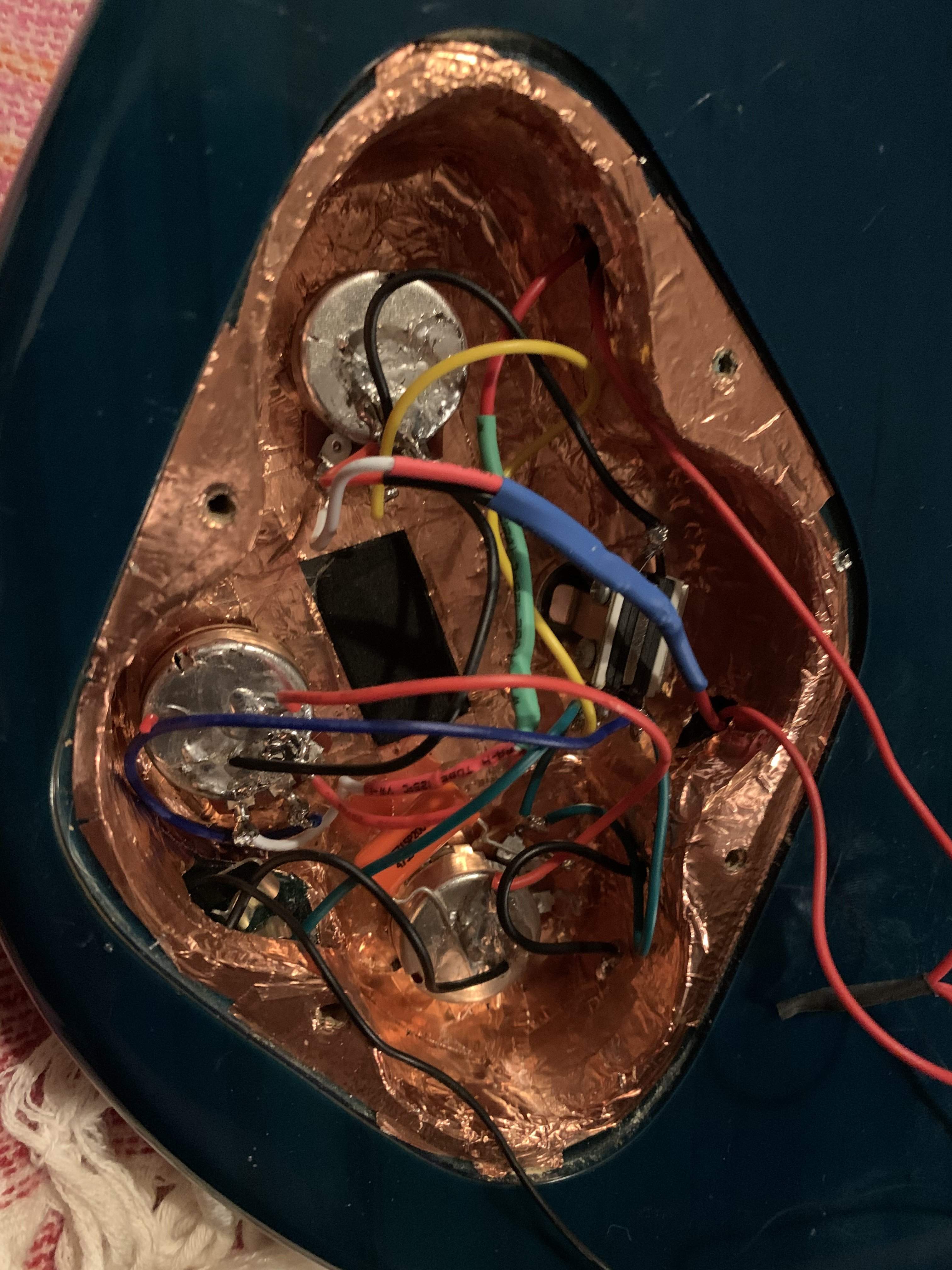
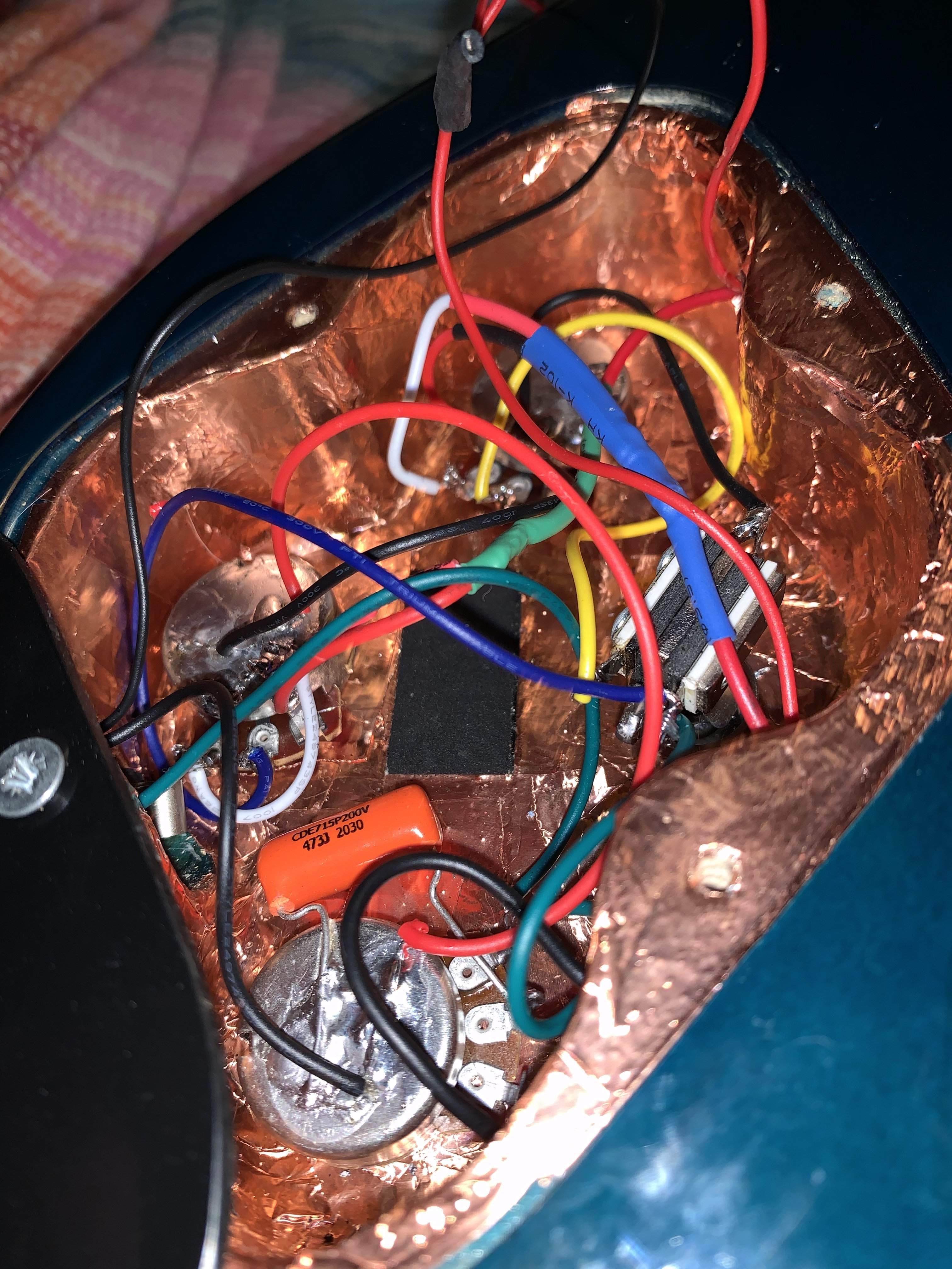
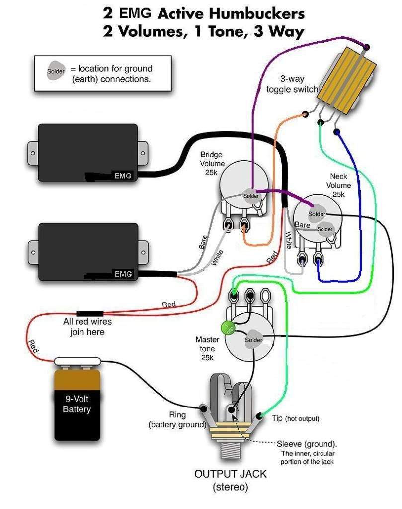
I've attached a couple pictures of the controls — I know my soldering is not pretty, but I don't think there are any cold solder joints, and I'm confident I didn't overheat the pots or anything. I assume I must have screwed something up with the wiring, but I've double- and triple-checked the wiring diagram and all the connections seem to be in the right place. Is there something I've wired incorrectly? Do my pickups need to be replaced or something? (I also attached the wiring diagram for reference.)
IMG_1774 copy.jpg
IMG_1771 copy.jpg
IMG_1772 copy.jpg
IMG_1775 copy.jpg
wiring diagram.jpg


Any help you guys can give is greatly appreciated - I don't mind starting it all over again (I like this kind of stuff), I just don't want to spend hours doing another rewire that won't work. Thanks in advance for any help/advice you can give!
 
You are running EMG's? I thought they needed something closer to a 25k pot than a 500k pot. (You diagram agrees with me.) Also, when you have a jack in a recessed, shielded area, it isn't the worst idea to make sure the jack isn't shorting against the side wall.

No, not running EMGs (no idea what pickups Brice used back then, though) - I just used the EMG diagram since it's the two pickup/V-V-T-3way/active configuration I'm going for in my bass.

Good idea on the jack; the original jack had a plastic housing but the new one doesn’t, so it could be shorting. I'll give that a try.
 
I'm just about at wit's end here, and I'm hoping somebody can help me figure out what I'm doing wrong.

I've been trying to rewire my 5-string fretless for a while now — I made a thread a few years ago asking about the specs/wiring diagram for it. Brice has since discontinued this bass (I've had it for like 15 years), and when I emailed them to ask for a wiring diagram they didn't even have one.

Long and short of it is, it's a Brice V2 with a weird factory control setup (V-V-B-T); since the blend control is pointless with two volume controls, it was suggested to me that I either replace the blend pot with a 3-way switch or install a "producer's knob" that doesn't really do anything.

I tried the producer's knob, but it didn't work, so I found a wiring diagram for a standard VVT configuration with a 3-way switch. I've swapped out all the pots (A500k for the volume controls, B500k for the tone), installed the switch, replaced the output jack (the metal leads on the original jack were falling apart). After the second most-recent attempt, I thought maybe I burned out the pots while soldering, so I bought all new pots, lined the whole thing with copper tape, and started from scratch, and it's still not working.

I've attached a couple pictures of the controls — I know my soldering is not pretty, but I don't think there are any cold solder joints, and I'm confident I didn't overheat the pots or anything. I assume I must have screwed something up with the wiring, but I've double- and triple-checked the wiring diagram and all the connections seem to be in the right place. Is there something I've wired incorrectly? Do my pickups need to be replaced or something? (I also attached the wiring diagram for reference.)View attachment 4032996View attachment 4032990 View attachment 4032991 View attachment 4032993 View attachment 4032997

Any help you guys can give is greatly appreciated - I don't mind starting it all over again (I like this kind of stuff), I just don't want to spend hours doing another rewire that won't work. Thanks in advance for any help/advice you can give!
I'm not sure about that diagram, but I'll just give you the run down on switches, as I have one in each of my basses. Center is where you run your hot and ground. Each position of the switch sends the center to each set of nodes that corresponds to switch postion. So, run leads from each set, to your pots in the way you want them set up (on/on/off/both on/whatever). Then, depending on switch position, the hot will go to its destination. You may have a bit of trial and error until you finally figure out what does what on your switch, but you'll get it.
20201027_195528.jpg


You could also simply run your grounds normally, and just run the hots on the switch. Either way.
 
  • Like
Reactions: ReeseyC
What pickups are you using? Most active pickups want very low resistance pots, not just EMGs.

On your photo, can you label the wires that go in/out of the channels? I.e. which ones are going to which pickups or the battery, etc.

Also can we get a better photo of the jack?

Do you own a multimeter to check that the pickups are getting voltage?
 
To tell you the truth, the schematic looks suspect. if I'm understanding the switch, it selects neck, bridge, or both pickups. The way the pots are wired If you select both pickups and either volume pot is turned down, it will short out the other pickup and you'll get nothing. The purple wire in the diagram from the switch to ground (black in your pictures) doesn't make sense to me. Maybe I don't understand the switch, but if that switch terminal connects to any other switch terminal in some switch position, it will short the signal to ground.

I would scrap the switch entirely (or leave it totally disconnected as a "producer switch" :D) and just use a standard passive jazz bass VVT schematic. In the standard jazz configuration, the pickup hot outputs go to the pot wipers (center lugs). This allows you to blend pickups and turn one down without shorting out the other.
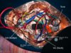
Something like this:

jbass wiring.png
 
What pickups are you using? Most active pickups want very low resistance pots, not just EMGs.

On your photo, can you label the wires that go in/out of the channels? I.e. which ones are going to which pickups or the battery, etc.

Also can we get a better photo of the jack?

Do you own a multimeter to check that the pickups are getting voltage?

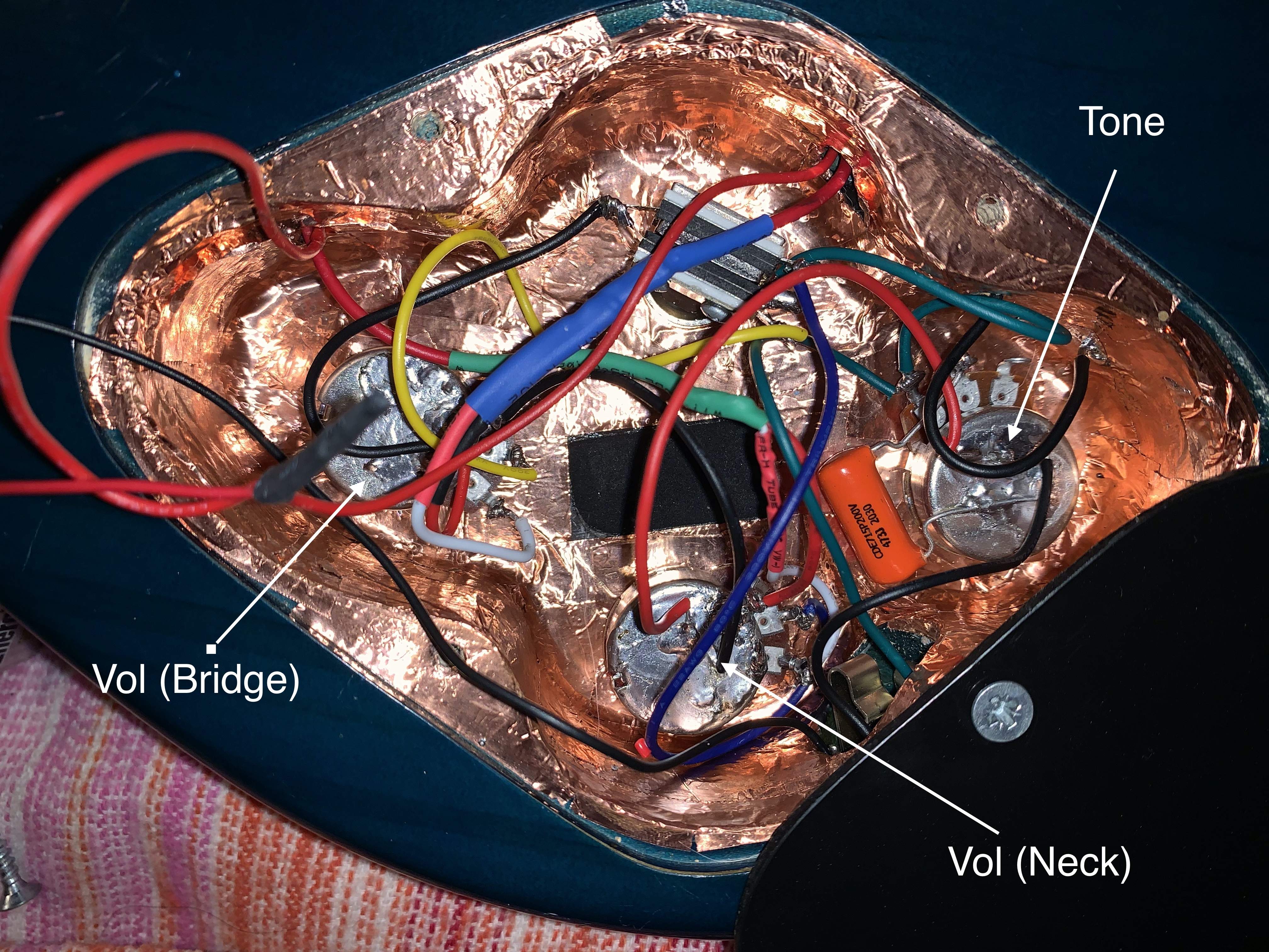
Here's a slightly updated pic - it's kinda crowded in there, so it's hard to label everything. I used the same color wires in the pic as the ones shown in the wiring diagram (except for the purple wire, which I didn't have so I used black there instead). I've also attached a pic of the jack too.

I do own a multimeter and touching the lugs does generate a reading; I don't know which setting I should be using on my multimeter to get the right values, but the readings are at least the same across all pots (not zero, obviously). Brice wiring (2).jpg IMG_1784 copy.jpg IMG_1785 copy.jpg
 
To tell you the truth, the schematic looks suspect. if I'm understanding the switch, it selects neck, bridge, or both pickups. The way the pots are wired If you select both pickups and either volume pot is turned down, it will short out the other pickup and you'll get nothing. The purple wire in the diagram from the switch to ground (black in your pictures) doesn't make sense to me. Maybe I don't understand the switch, but if that switch terminal connects to any other switch terminal in some switch position, it will short the signal to ground.

I would scrap the switch entirely (or leave it totally disconnected as a "producer switch" :D) and just use a standard passive jazz bass VVT schematic. In the standard jazz configuration, the pickup hot outputs go to the pot wipers (center lugs). This allows you to blend pickups and turn one down without shorting out the other.
Something like this:

View attachment 4033584
I'm totally willing to scrap the switch if necessary; I basically just wanted something to fit in the fourth slot where the blend pot used to be and I figured a switch was as good an option as any. But it sounds like it's actually more trouble than it's worth having it in there :D

Two questions:

1) Does the switch need to be grounded or anything? I thought I'd read somewhere that even if a knob or switch is disconnected from the wiring sequence, it still needs to be wired to something so it doesn't create interference. But I could be wrong on that.

2) Do you know where I could find a wiring diagram for active pickups? (I moved the battery out of the way in the pictures to make it easier to follow the wiring.)
 
I do own a multimeter and touching the lugs does generate a reading; I don't know which setting I should be using on my multimeter to get the right values, but the readings are at least the same across all pots (not zero, obviously). View attachment 4033652 View attachment 4033654 View attachment 4033655

Take the battery out. Set your multimeter for resistance. Look for open signal (high resistance between connections to that should have continuity and look for shorts (low or zero resistance) between connections that should not be talking to each other. Anything with a resistor or pot in the circuit could conduct, but I would just check your soldering first.

p.s. look for shorts to ground where their shouldn't be. You have a lot of stuff going on in there.

Then put the battery and switch to voltage readings and follow the signal path. You don't have too many things connected so you should be able to use your diagram to trace things and make sure pots are working.
 
This is where I get out my DVM and start chasing things. The solder work is suspicious (as you noted). Easy to check with a DVM, less so easy by eye.
Agreed, the solder work isn't perfect, but I'm fairly confident there are no cold solder joints. Even if there were, it's my understanding that cold soldering typically leads to issues down the road but not necessarily right away, no?

I'll try to take a look with my multimeter, but I still don't really get what I'm doing when I use it, to be honest. Thus far my approach has been "Does it generate a reading? Is the reading the same across all pots with the same values? Does the reading change when I turn the knob?" which probably isn't quite right.
 
Agreed, the solder work isn't perfect, but I'm fairly confident there are no cold solder joints. Even if there were, it's my understanding that cold soldering typically leads to issues down the road but not necessarily right away, no?
One cold solder joint can shut down the whole thing. Also, you are dealing with weak signals and low current, so unlike a high power circuit, a bad solder joint will kill you - it is not about poor performance - you'll get nothing. :)

I'll try to take a look with my multimeter, but I still don't really get what I'm doing when I use it, to be honest. Thus far my approach has been "Does it generate a reading? Is the reading the same across all pots with the same values? Does the reading change when I turn the knob?" which probably isn't quite right.
To check the circuit properly, you would need a constant input signal at the pickups output (like constant strumming). You'd follow that very weak signal to where it gets amplified all the way to the output jack. (here, you would need to follow AC not DC voltage). The 9V battery is just powering the internal amps.

In any case, you can check the pots. I doubt the pots themselves are bad, but you can look at the resistance change between the center tap and outer tap of any pot and should see a variable resistance as the knob is turned.

Check your solder work first. If it is all good, then you have more work to do. It could easily be mis-wired too. I have a bass that the pots were connected backwards at the factory. For kicks, I never fixed it.
 
  • Like
Reactions: RBrownBass
This is what I'd do.

First test - signal path. Put selector switch in "both" and all knobs full on. Set meter to resistance. Pull the battery. Insert a cable and clamp one lead to the tip at the other end of the cable. Now, with the other lead, touch it to the lug on the volume pots (one at a time) where the signal wire from the pickup is connected. That should give a very low resistance reading. If it does not, trace the signal path (volume pot to selector switch to tone to jack). Something is broken or not wired correctly.

Next, with the same setup, touch the free lead to ground. You should get a very high reading (in the k's). If it's a low reading, like in the single digits or dozens of ohms, your signal path has a short to ground. Check the jack, a jack in a shielded pocket like that can short easily. Sometimes the short doesn't happen unless there's a cable in, since that causes the contacts to move a bit.

If that's all ok I would check the ground wiring including the battery. Keep the meter on resistance. Keep the cable plugged in. Clip one meter lead to the sleeve at the other end of the cable. Touch the free lead to a known ground in the cavity, i.e. the back of a pot or the shielding. You should get a very low reading. If there's no continuity or a very high reading, you have a bad ground, probably at the jack. If that's good, keep the same setup and touch the free probe right where the ground wire from each pickup goes - it looks like your pickups are grounded through shielding on the cable so touch it to where that shield is soldered - looks like you've got it on the volume pots. Again, if you get a high resistance or open circuit, you have a bad ground somewhere.

Now, keep the same setup, and put the free probe on the ground terminal on your battery harness. You should get zero resistance or a low reading. In basses with active pickups, the battery is switched on and off via wiring the battery ground to the ring terminal on the jack, so when a cable is inserted the sleeve on the cable shorts the ring and sleeve teminals on the jack together. Since the sleeve terminal on the jack is grounded to the rest of the wiring, that grounds the battery. If you have the jack wired wrong and the battery isn't getting "turned on" by connecting it's ground, you'll get no sound.

Finally, plug the battery in, leave the meter set up as it was (one probe clamped to the ground on the inserted cable), and switch the meter to DC voltage. Now, touch the free probe to the power lead running to each pickup. You should see 9v (or negative 9v depending on the probe orientation). If you don't, your battery is wired wrong.

If none of those tests reveal a problem let us know and we can move on.
 
  • Like
Reactions: Basslice
I'm totally willing to scrap the switch if necessary; I basically just wanted something to fit in the fourth slot where the blend pot used to be and I figured a switch was as good an option as any.

No reason to ditch the switch unless you don't want it.

1) Does the switch need to be grounded or anything? I thought I'd read somewhere that even if a knob or switch is disconnected from the wiring sequence, it still needs to be wired to something so it doesn't create interference. But I could be wrong on that.

There doesn't need to be any grounding on the switch for it to function properly. If the switch not being grounded was the problem, your symptoms would be different. You'd still get a signal out, at least. And at any rate since you have shielding tape inside the cavity, the chassis of the switch is likely grounded through physical contact with the shielding anyways.

2) Do you know where I could find a wiring diagram for active pickups? (I moved the battery out of the way in the pictures to make it easier to follow the wiring.)

Who made the pickups? Most suppliers have wiring diagrams on their websites, but they're all pretty universal. An active pickup typically has a signal and ground which are treated the same way as the leads from a passive pickup, plus a positive lead which gets connected to the positive lead from the battery. Sometimes the signal and ground are just one shielded cable, where the signal is the inner wire and the braided shield is the ground.

Active pickups need a stereo jack so you can switch the battery ground via the jack, as I mentioned above.
 
  • Like
Reactions: ReeseyC
The way the pots are wired If you select both pickups and either volume pot is turned down, it will short out the other pickup and you'll get nothing.
Every two-pickup Gibson guitar is wired this way, it's not "suspect", it's just different.

Whoa, what's going here? Is that capacitor lead touching the the other pot terminal??? That can create a short circuit.

bad_touch.jpg
 
A 3-way switch AND dedicated volume controls for each pickup? It's like adding another gas pedal to your car, IMO. So to (hopefully) offer some help, firstly I would really reconsider what you NEED the controls to do because the redundancy makes for jumbled wiring.

Once you figure out what you need, I would drop it off at a repair shop. It should set you back about $50.
 
  • Like
Reactions: ReeseyC