
Enjoy the benefits of a premium membership!
Upgrade Account
-
TalkBass has been independent since 1998. Add your voice.
Create a free account to reply to discussions, view embedded media, and browse with fewer display ads.
Join free Log in
Want zero display ads or expanded classifieds tools? Compare plans.
You are using an out of date browser. It may not display this or other websites correctly.
You should upgrade or use an alternative browser.
You should upgrade or use an alternative browser.
Full Scale templates
- Thread starter jcomea
- Start date
More options
Who Replied?

headlikeahole
Commercial User
mikeyswood
Inactive
I draft in AutoCad and then print to a 36x48 pdf. A quick trip to Kinko's and $10 makes life easy in the shop:
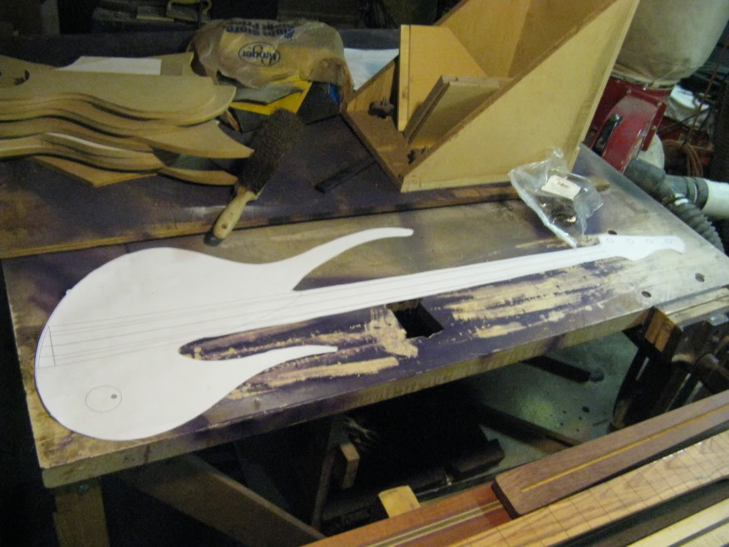
And from there I make the templates:
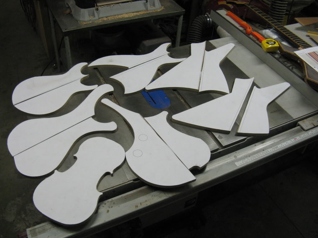
And from there I make the templates:

I just draw mine out on paper real size with a pencil, cut them out and trace the shape on the wood.
Dirk
Dirk

gbarcus
Commercial User
- Jul 20, 2008
- 398
- 12
- Disclosures
- Owner of Barcus Basses barcusbasses.com
One way you could do this is to find the ratio your sketch is to full size then draw a grid on your sketch. Get cardboard or foamboard and draw a grid that will allow you to transfer your sketch full size.

mikeyswood
Inactive
gbarcus
Commercial User
- Jul 20, 2008
- 398
- 12
- Disclosures
- Owner of Barcus Basses barcusbasses.com
Scan as image, print to pdf, then scale to fit the size you want.
That's just way too easy.

Scan as image, print to pdf, then scale to fit the size you want.
Or scan as PDF, one less step
lowsound

I'm pretty spoiled because I work for a civil engineering company and have access to wide format plotters. Usually I'll just draft up my designs in AutoCad and then plot them direct to any size paper I need.
mikeyswood
Inactive
I'm pretty spoiled because I work for a civil engineering company and have access to wide format plotters. Usually I'll just draft up my designs in AutoCad and then plot them direct to any size paper I need.
How does this post help the OP?

I designed my V bass on paper first, then transferred the design to my computer. To do that, I drew a rectangle around the design to get the overall dimensions (in my case, 16" wide and 24"). I then drew a center line down the vertical axis, which bisected the body parallel with the direction of the strings. Then I used an adjustable protractor and 18" steel ruler to measure dimensions off the corners and the center line. I then transferred those dimensions into my CAD for idiots program, Invalid Link Removed. After I adjusted and tweaked the design in that program, I printed to PDF using CutePDF and had FedEx Office (Kinkos) print it on their plotter.
Then, as Mikey showed, you just glue it to your favorite template material and cut it out.
How does yours, for that matter?
Then, as Mikey showed, you just glue it to your favorite template material and cut it out.
How does this post help the OP?
How does yours, for that matter?
mikeyswood
Inactive
How does yours, for that matter?
Which one: the one addressing the OP's original post, or the one addressing his amended post?
Both of them provide solutions that help the OP get to his destination.

I design my instruments in an older version of AutoCad (AutoCad LT 2003) and print out my patterns myself in a normal desktop inkjet printer. The trick is to establish a set of gridlines on the drawing so that you can print out a pattern in multiple sheets, and get them lined up correctly.
For example, a body will normally have to be printed out in four sheets. In AutoCad, I draw a grid of red lines over the body that break it up into four 7" x 10" rectangles. Print out the four sheets, and each has the red rectangle of grid lines on it. Trim them with scissors and tape them together, lining up the red lines.
Tip: When I print patterns, I print them on thicker 28lb paper (called cover stock or card stock), rather than normal paper. The card stock will feed better through the printer, usually giving you better accuracy along the long direction. Thin paper will tend to slip along the feed direction and cause inaccuracies. Inkjet printers are surprisingly accurate, in my experience, if the paper feeds correctly.
That's another reason for the grid lines. If you draw them in your Cad program as exactly 7.000" x 10.000", then you can use them to test your printout. Put a good ruler on each sheet and verify that the grid lines are exactly to dimension. If not, print it again, or find the problem.
To answer your other question: If you're starting with an undersized pencil sketch, and want to get to an accurate Cad-generated pattern, here's the process:
First, scan in your pencil sketch, which will give you a .jpg image file. Then, in your Cad program, start a new drawing and import the jpg file into it. There's usually a function like Insert Image, or something. Then, in the Cad program, draw up a framework of lines on a new layer to establish the dimensions that you know. For example, if you're working on a body shape, draw in some lines to show the length and width that you want it to end up. Then, move the image file under that framework of lines and stretch it, scale it, or expand it as needed to fit those dimensions. Finally, you redraw the curved lines in the image, drawing new Cad polylines right over the lines in the image. Then you can shut off the image file layer and go to work adding details to your Cad file.
For example, a body will normally have to be printed out in four sheets. In AutoCad, I draw a grid of red lines over the body that break it up into four 7" x 10" rectangles. Print out the four sheets, and each has the red rectangle of grid lines on it. Trim them with scissors and tape them together, lining up the red lines.
Tip: When I print patterns, I print them on thicker 28lb paper (called cover stock or card stock), rather than normal paper. The card stock will feed better through the printer, usually giving you better accuracy along the long direction. Thin paper will tend to slip along the feed direction and cause inaccuracies. Inkjet printers are surprisingly accurate, in my experience, if the paper feeds correctly.
That's another reason for the grid lines. If you draw them in your Cad program as exactly 7.000" x 10.000", then you can use them to test your printout. Put a good ruler on each sheet and verify that the grid lines are exactly to dimension. If not, print it again, or find the problem.
To answer your other question: If you're starting with an undersized pencil sketch, and want to get to an accurate Cad-generated pattern, here's the process:
First, scan in your pencil sketch, which will give you a .jpg image file. Then, in your Cad program, start a new drawing and import the jpg file into it. There's usually a function like Insert Image, or something. Then, in the Cad program, draw up a framework of lines on a new layer to establish the dimensions that you know. For example, if you're working on a body shape, draw in some lines to show the length and width that you want it to end up. Then, move the image file under that framework of lines and stretch it, scale it, or expand it as needed to fit those dimensions. Finally, you redraw the curved lines in the image, drawing new Cad polylines right over the lines in the image. Then you can shut off the image file layer and go to work adding details to your Cad file.
What I have done is to buy a roll of craft paper that is 24 inches wide. I cut off a piece long enough for a whole bass and then just reproduce it freehand. If the original sketch was just freehand I am guessing it wasn't done to exacting tolerances, so amazing accuracy in its reproduction won't likely be necessary. In fact, as you draw it out again you may find yourself altering it slightly to suit your tastes when you see it full size and compare it to existing basses you may have.
Hi im very new to talk bass,my question is: does anyony have any free bass body templates or can any one point me in the direction of any free PDF print outs?
Im quite up to date with a build as i have done a few many years ago.
Im doing a project for my young sone,body shape not important, i have a pair of soap bar pickups all the active pots and a maple fretless p/type neck. Any help from anyone would be fantasic, cheers all. Regards Alan.
Im quite up to date with a build as i have done a few many years ago.
Im doing a project for my young sone,body shape not important, i have a pair of soap bar pickups all the active pots and a maple fretless p/type neck. Any help from anyone would be fantasic, cheers all. Regards Alan.


