This contains interesting modifications so read past the prelog.
Disclamer: never EVER try anything like this at home kids, get a 4 year (or more) degree before you even TRY to tinker with things. I'm just a simple tech messing with things I don't really know about and if I create a singularity or a rip in time space I apologize profusely.
You will see that I have questioning opinions hear about some of the things that I've done and that's okay too. My stuff, idc. Anyway, if you choose to modify anything of your own and use any of my ideas more power to you!
The last couple of days when I wasn't messing with my new Quilter Bass Block 800 I've been tube rolling my SVP-PRO and SVPCL for fun.. my SVP-PRO developed a buzzing at high volume and I suspected a bad connection due to the physical movement, so, I tore it apart and found the bad connection and touched up everything else (bad connection was pin 1 on J21)
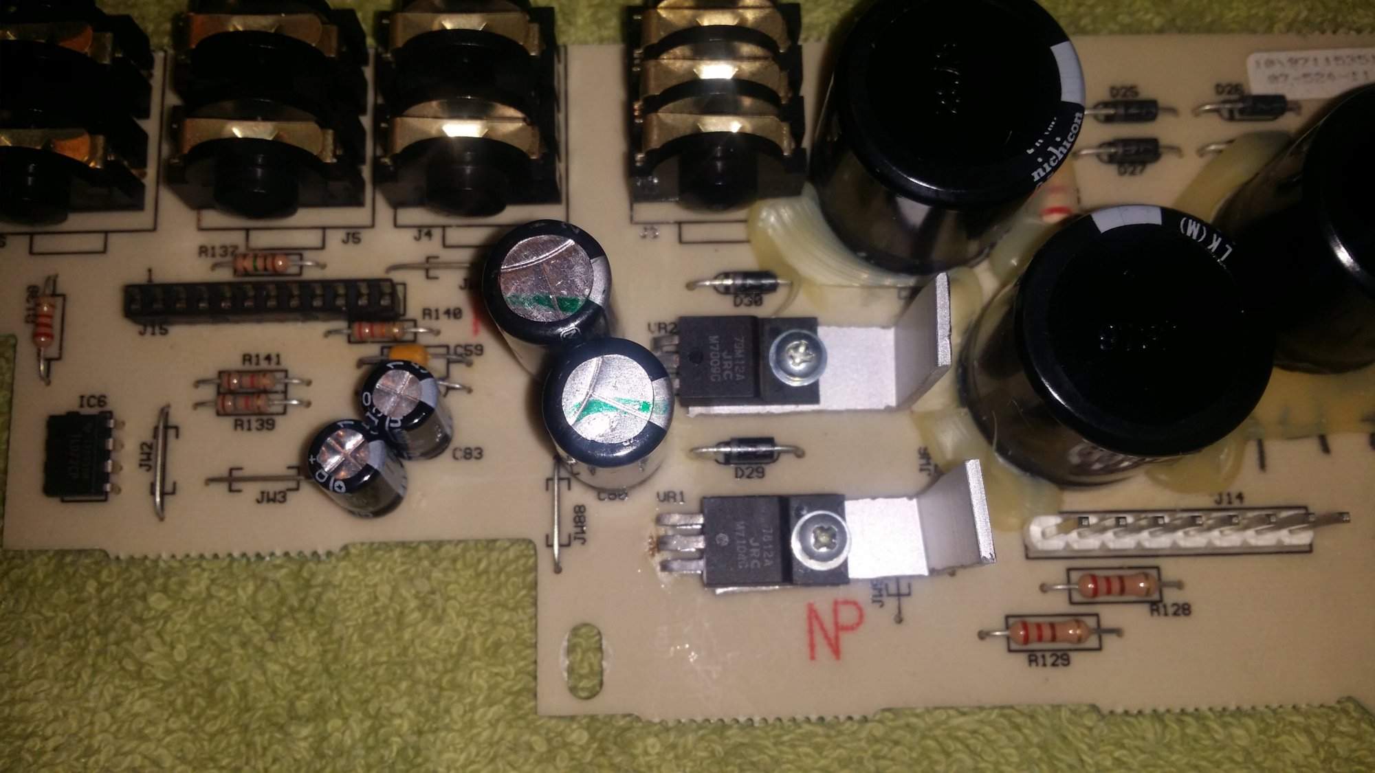
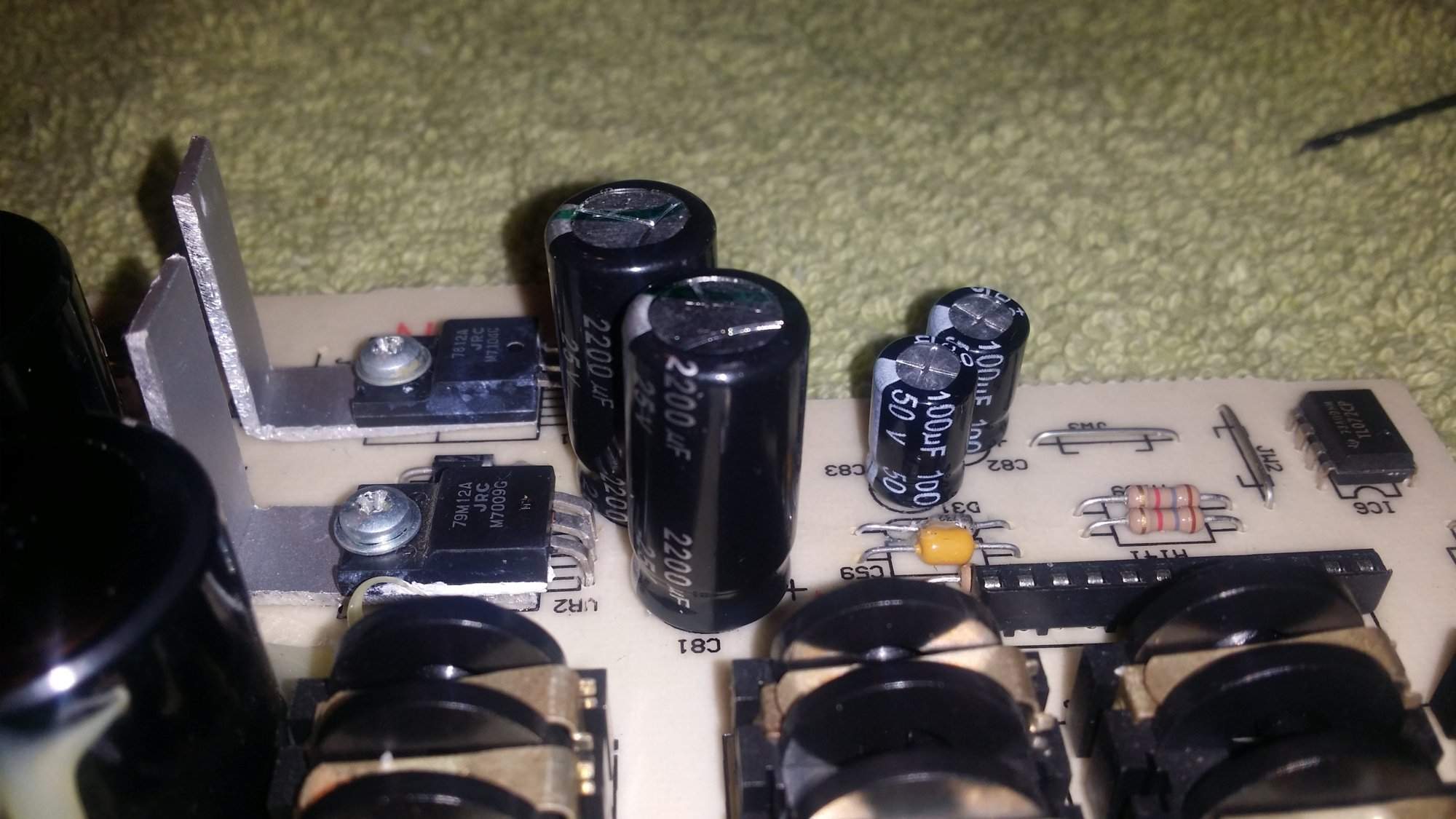
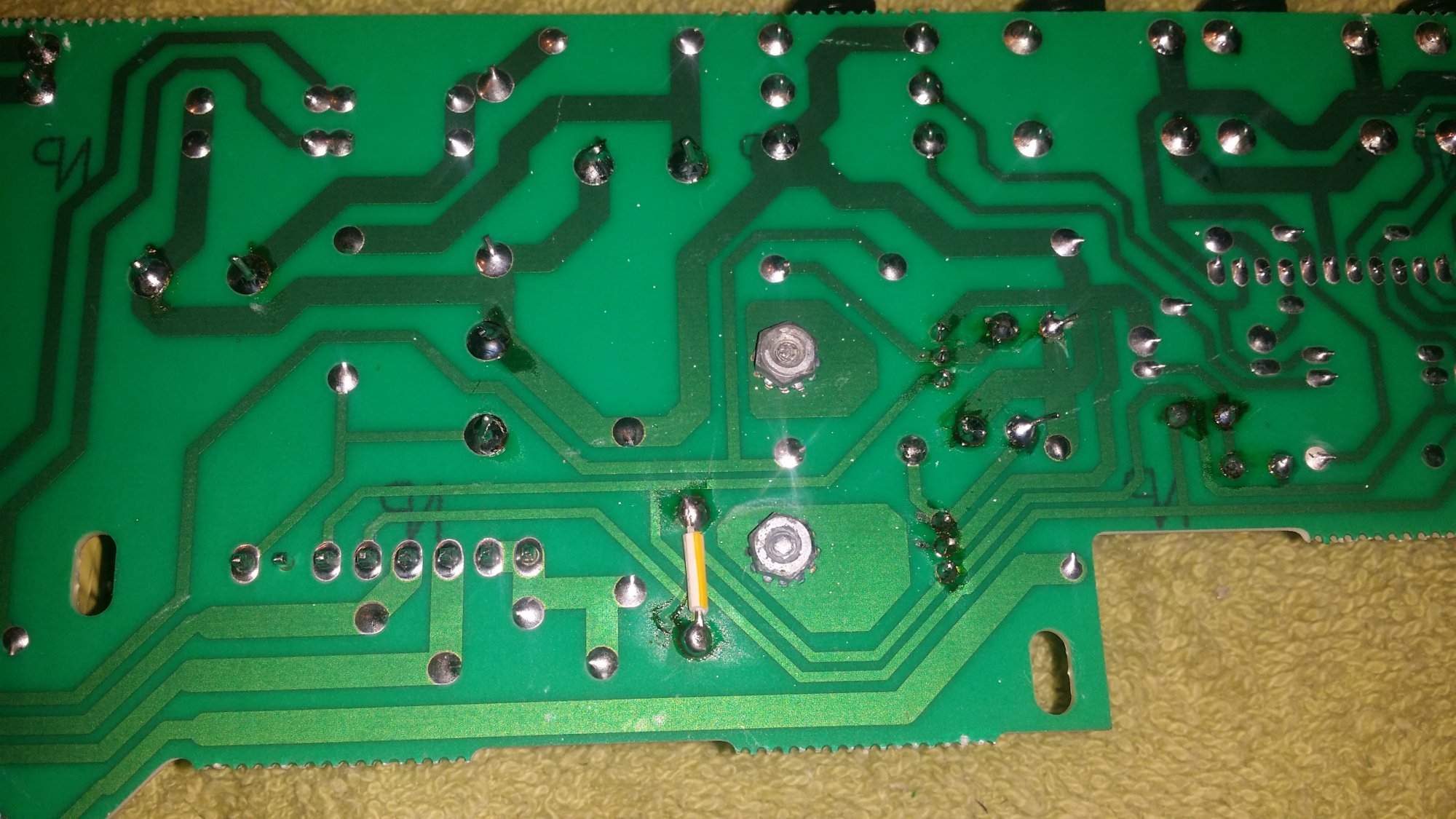
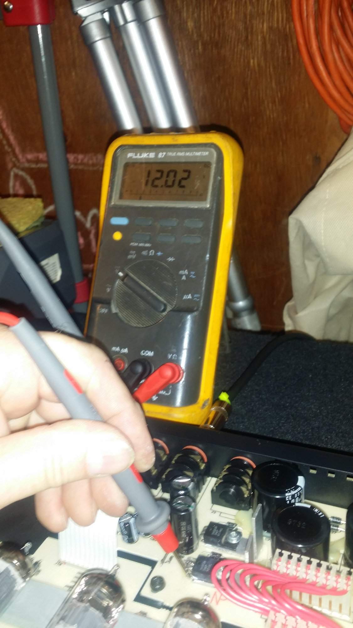
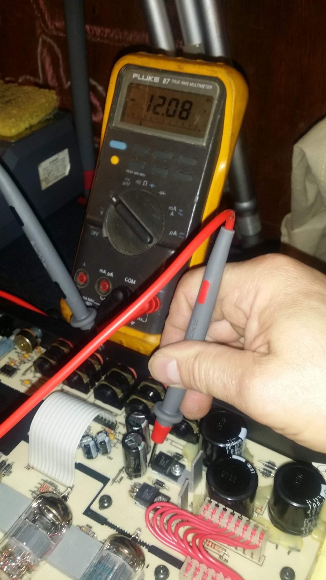
Anyway, there's been talk about the preamp and how it's +- 8 VDC rails seemed a bit low and conjecture that this preamp may be better if the DC rails to the front were a bit higher. Giving the preamp and the EQ more headroom. So, yeah... I yanked out the LM79-8 and LM78-8 and replace them with LM79-12 and LM78-12 added heatsinks, just because, and upgraded the filter caps on both sides. The transformer seems has enough headroom to deliver the voltage needed, there's usually enough headroom engineered in and the solid state components don't draw a huge amount of current anyway. See pictures below.
So far, it's working, no problems!
It's early here and I can't crank it but it's sounding like a champ. I'll keep your posted. Right now I'm upgrading the fan power supply for the fan I had installed previously (I lost an SVP-PRO when a transformer failed due to internal heat, so I added a cooling fan to this one). The +12V rail was dipping with the fan on it so I added a separate power supply for the fan. I'll add those pictures when I finish.

Disclamer: never EVER try anything like this at home kids, get a 4 year (or more) degree before you even TRY to tinker with things. I'm just a simple tech messing with things I don't really know about and if I create a singularity or a rip in time space I apologize profusely.
You will see that I have questioning opinions hear about some of the things that I've done and that's okay too. My stuff, idc. Anyway, if you choose to modify anything of your own and use any of my ideas more power to you!
The last couple of days when I wasn't messing with my new Quilter Bass Block 800 I've been tube rolling my SVP-PRO and SVPCL for fun.. my SVP-PRO developed a buzzing at high volume and I suspected a bad connection due to the physical movement, so, I tore it apart and found the bad connection and touched up everything else (bad connection was pin 1 on J21)
Anyway, there's been talk about the preamp and how it's +- 8 VDC rails seemed a bit low and conjecture that this preamp may be better if the DC rails to the front were a bit higher. Giving the preamp and the EQ more headroom. So, yeah... I yanked out the LM79-8 and LM78-8 and replace them with LM79-12 and LM78-12 added heatsinks, just because, and upgraded the filter caps on both sides. The transformer seems has enough headroom to deliver the voltage needed, there's usually enough headroom engineered in and the solid state components don't draw a huge amount of current anyway. See pictures below.
So far, it's working, no problems!
It's early here and I can't crank it but it's sounding like a champ. I'll keep your posted. Right now I'm upgrading the fan power supply for the fan I had installed previously (I lost an SVP-PRO when a transformer failed due to internal heat, so I added a cooling fan to this one). The +12V rail was dipping with the fan on it so I added a separate power supply for the fan. I'll add those pictures when I finish.
Last edited: