• TalkBass has been independent since 1998. Add your voice.
    Create a free account to reply to discussions, view embedded media, and browse with fewer display ads.
    Join freeLog in
    Want zero display ads or expanded classifieds tools? Compare plans.

Radio Interference - Can't solve it

I forgot that in all of the focus on the basses, that I'm also getting the radio through my powered monitors, whether or not they're plugged into the interface.

So it seems to suggest that at least part of the problem is from the station's end.
 
Today's update...

I reached out to the local amateur radio club. A couple people responded. One of them came out to my place today to take a look. As it turns, he also happens to be the guy who built the radio tower. He shared that at 6000 Watts, less than 900 feet from me, *and* that one of the antennas is pointing straight at my house, there's not really anything that can be done. He agreed that the preamps are picking up the signal. Given the strength and direction of the signal, he said that the demodulating piece didn't really matter. He took one of my instrument cables to his workshop and will solder a .01uF caps to see if that will stop the signal. It might be possible to solder one of these caps onto the the preamps, but figuring out where might not be so easy.

So, unfortunately, there may not be anything that I can do to get rid of the FM signal, other than move. :-(
 
  • Like
Reactions: steve_ss and WRM
The possibility of a .01uF cap stopping the signal is one of several ways to make a signal trap. The frequency to be trapped must be known, then calculations done to determine the components for the trap. It has been too many years since I worked with radios for me to suggest components for your situation. For an explanation of what this involves check this website. The situation of FM radio pickup by a TV is similar to yours.
Why Would I Need An FM Filter?
 
  • Like
Reactions: BaileyMan
The possibility of a .01uF cap stopping the signal is one of several ways to make a signal trap. The frequency to be trapped must be known, then calculations done to determine the components for the trap. It has been too many years since I worked with radios for me to suggest components for your situation. For an explanation of what this involves check this website. The situation of FM radio pickup by a TV is similar to yours.
Why Would I Need An FM Filter?
Where might I learn about how to do these calculations? The frequency 104.9 MHz.
 
Since FM is way higher frequency than audio, you could probably get by with a low pass filter. But did you try the ferrites? They usually work for these problems.
I had ordered some, but they were left out of the Amazon package. I've got some more on the way.

I don't think the ferrite clips will work for the basses since the signal is entering at the preamp.

For my powered monitors, I tried a larger ferrite core that I wrapped the speaker cable around a few times. That seems to have worked. It's big and wasn't cheap though, so I'm hoping the smaller clips will help out.

I've still got to figure out how/where/if possible to add a capacitor to the preamps in the basses.
 
Last edited:
  • Like
Reactions: steve_ss
This article explains how cable capacitance and circuit resistance form a low pass filter. The .01 uF capacitor is the same value as a 10,000 pF capacitor. So the guitar cable has a much smaller influence on the low pass filter than adding a .01 uF capacitor.

Guitar Cable Capacitance and Resonant Frequency

This article shows cable capacitance for several different guitar cables, albeit cables available in the UK, not so much in the US.

Guitar Cable Capacitance and Resonant Frequency

What is not given is the knee of the low pass filter formed. This because the circuit resistance must be known as well. Because the circuit resistance depends upon both the guitar output impedance and the amplifier input impedance, it is may be necessary to actually measure the circuit impedance using a multi-meter, as described in this article.

Invalid Link Removed

This article mentions that typical amplifiers are considered to have high impedance inputs, with 100K ohms being common.

https://gollihurmusic.com/ohms-impedance-from-the-input-perspective/

Use this online calculator to see how an RC filter rolls off the frequency response. Please note that the roll-off is essentially a straight line of about 3 dB per octave. This a very gradual slope. Assuming that the highest frequency you need to send to the amplifier is 20 kHz, then the 104.9 MHz signal of the radio station is over 15 octaves higher. This gives approximately a 45 dB reduction of the radio station frequency to the amplifier. This may or may not be a sufficient reduction, depending upon the actual strength of the radio station at your equipment location.

RC Low-Pass Filter Response Interactive Calculator

Please understand that these calculations are approximate and will not truly describe your equipment with a .01 uF capacitor added to the circuit.
 
You could try putting ferrite cores on the pickup leads in the basses.
Assuming this does work, wouldn't it only work if the pickup wires were acting as the antenna?

I've confirmed with one bass that it's the preamp and not pickups by disconnecting the pickups from the pre.

I'd also need some pretty small ferrite cores. I don't know if they exist. I'm pretty out of my league with all this...
This article explains how cable capacitance and circuit resistance form a low pass filter. The .01 uF capacitor is the same value as a 10,000 pF capacitor. So the guitar cable has a much smaller influence on the low pass filter than adding a .01 uF capacitor.

Guitar Cable Capacitance and Resonant Frequency

This article shows cable capacitance for several different guitar cables, albeit cables available in the UK, not so much in the US.

Guitar Cable Capacitance and Resonant Frequency

What is not given is the knee of the low pass filter formed. This because the circuit resistance must be known as well. Because the circuit resistance depends upon both the guitar output impedance and the amplifier input impedance, it is may be necessary to actually measure the circuit impedance using a multi-meter, as described in this article.

Invalid Link Removed

This article mentions that typical amplifiers are considered to have high impedance inputs, with 100K ohms being common.

https://gollihurmusic.com/ohms-impedance-from-the-input-perspective/

Use this online calculator to see how an RC filter rolls off the frequency response. Please note that the roll-off is essentially a straight line of about 3 dB per octave. This a very gradual slope. Assuming that the highest frequency you need to send to the amplifier is 20 kHz, then the 104.9 MHz signal of the radio station is over 15 octaves higher. This gives approximately a 45 dB reduction of the radio station frequency to the amplifier. This may or may not be a sufficient reduction, depending upon the actual strength of the radio station at your equipment location.

RC Low-Pass Filter Response Interactive Calculator

Please understand that these calculations are approximate and will not truly describe your equipment with a .01 uF capacitor added to the circuit.
Thanks for taking the time to gather tthese links and for your response. I'll have to go through it a few times I'm sure before it all makes sense.

I'll post back up when I have an update.
 
Other considerations:
If the 3 dB/octave RC filter does not attenuate the radio station interference, then adding a second RC low pass filter stage will reduce the interference by 6 dB/octave. This article illustrates the difference between a single-order (one stage RC circuit) and a second-order ( two stage RC circuit) low pass filter.

Link Removed

There will be some signal loss and phase shift with any filter. Hopefully, these effects will not be audible.
 
  • Like
Reactions: BaileyMan
This article explains how cable capacitance and circuit resistance form a low pass filter. The .01 uF capacitor is the same value as a 10,000 pF capacitor. So the guitar cable has a much smaller influence on the low pass filter than adding a .01 uF capacitor.

Guitar Cable Capacitance and Resonant Frequency

This article shows cable capacitance for several different guitar cables, albeit cables available in the UK, not so much in the US.

Guitar Cable Capacitance and Resonant Frequency

What is not given is the knee of the low pass filter formed. This because the circuit resistance must be known as well. Because the circuit resistance depends upon both the guitar output impedance and the amplifier input impedance, it is may be necessary to actually measure the circuit impedance using a multi-meter, as described in this article.

Invalid Link Removed

This article mentions that typical amplifiers are considered to have high impedance inputs, with 100K ohms being common.

https://gollihurmusic.com/ohms-impedance-from-the-input-perspective/

Use this online calculator to see how an RC filter rolls off the frequency response. Please note that the roll-off is essentially a straight line of about 3 dB per octave. This a very gradual slope. Assuming that the highest frequency you need to send to the amplifier is 20 kHz, then the 104.9 MHz signal of the radio station is over 15 octaves higher. This gives approximately a 45 dB reduction of the radio station frequency to the amplifier. This may or may not be a sufficient reduction, depending upon the actual strength of the radio station at your equipment location.

RC Low-Pass Filter Response Interactive Calculator

Please understand that these calculations are approximate and will not truly describe your equipment with a .01 uF capacitor added to the circuit.
I used this RC low pass filter calculator as I was able to specify values more easily.
Invalid Link Removed

But, as I'm typing and deleting and typing again and deleting again, I realize I need some help understanding some details.

If the radio signal is entering the preamp somewhere after its input, adding an RC low pass filter before the preamp input (e.g. between the balance pot and preamp input) wouldn't do anything because the signal is being picked up somewhere after that. Similarly, adding a low pass filter to the preamp output also wouldn't do anything to attenuate 104.9 MHz, because it's already been transformed to frequencies in the audible range.

So then I would have to know where in the preamp the 104.9 MHz is being picked up.

Given that the volume and tone knobs affect the radio signal differently in the different preamps (East, Aguilar, Bartolini), would that be a clue as to where the radio signal is coming in? E.g. one preamp the tone knobs don't change the tone of the radio signal, but the volume does. Therefore the radio must be getting picked up somewhere after the tone part of the circuit before the volume. In another preamp the volume knob and tone knobs affect the radio signal, so it must be coming in before the tone and volume parts of the circuit.

So, if I figure out where the 104.9 MHz radio signal enters the preamp, that's where I'd wire in a capacitor of the appropriate value given the resistance / impedance of the circuit before it?

Possibly I'd be able to do this on the East preamp, although at risk of damaging it with my intermediate level, amateur soldering skills. Since the Aguilar and Bartolini preamps are encased in plastic, this probably won't be possible.

Am I on track with my understanding?
 
You raise good points. Without measuring actual signal frequencies and levels, it can only be guessed where the radio station signal (RFI) is actually entering the signal path. Either an oscilloscope, RF wave analyzer, or RF spectrum analyzer is used for this purpose. Please note that an oscilloscope capable of showing 200 MHz or higher is necessary.

The pre-amp may be demodulating the RFI (FM signal), which then enters the audio signal path. As you have tried shielding the control cavity on the bass guitar, adding a low pass filter will require modifying the circuitry of the pre-amp. This not something that I recommend trying. Better to replace the pre-amp with one that does not cause the problem.

The pre-amp may be boosting the RFI level, which is then demodulated by circuitry within the bass amplifier or a pedal. Inserting a low pass filter between the bass guitar output and the amplifier, or pedal, input should reduce the RFI. Adding a .01 uF capacitor to the guitar cable works this way. If the single capacitor does not eliminate the problem, then making a box to contain a second-order filter may be the best approach. The second-order can be passive or active, depending upon what signal strength is needed at the amplifier input.

Regarding your question about where to add a capacitor, please consider my comment about not trying to modify the circuit.

Perhaps, if the schematic diagrams for each of the pre-amps in question are available, then it may be possible to understand where the RFI is being demodulated and insert a capacitor before that circuit stage.
 
If you're hearing the signal, it's been translated into the audio frequency range and there's nothing you can do without affecting the bass sound. Messing with the component level of the preamp seems destined to failure as well. I would recommend making sure the electronics cavity is as surrounded as possible (copper tape Faraday cage) and then working on ways to keep FM signal from coming in on the wires. Whether that is as easy as a ferrite or needs a low pass filter, I don't know. The jack should be shielded and OK, so any other wires coming in are suspect--pickup wires, battery wires if they're in a separate battery box, bridge ground, etc.
 
Thanks @SharpCat and @TheSpinDoctor.

Yeah. I think I'm not going to start soldering capacitors on to these preamps. Like y'all have said, recipe for disaster.

I think my shielding is pretty good. Is it 100% perfect? Maybe not. I've read in other places that getting it 100% is actually quite hard.

So, I'll see if I can add ferrite cores or clips to some wires in there and see what happens.

I can always play in passive mode, so I'm not totally SOL, but I'd like to be able to play my active basses without that RFI.

Pretty frustrating. I also recognize it's a first world problem...
 
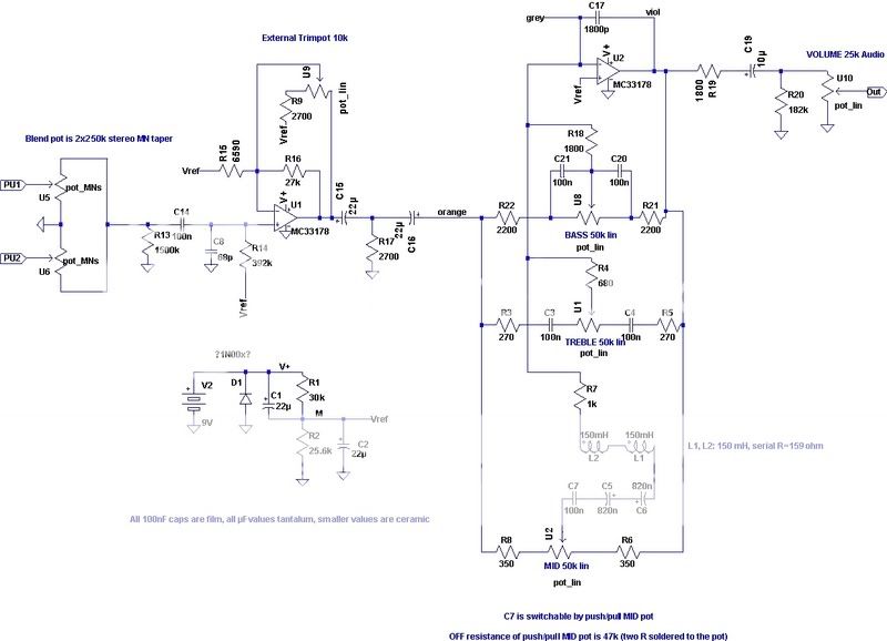
Found this schematic for the Bartolini NTMB3 pre-amp. Maybe used by Aguilar? The MC33178 is a dual operational amplifier, low noise and low supply voltage. Without going into FM demodulator circuit design, it is posible that the parallel connection of the MID tone circuitry with the BASS and/or TREBLE circuitry forms an FM demodulator. (The inductors in parallel with the capacitors forms a crude tuner. FM receiver design is not my forte.) Try varying the MID control position and observe for any change in the RFI. If the RFI does change, then the reason for your active basses picking up the radio station may be explained. Then, adding additional capacitance or a low pass filter can be considered.
NTMBschem.jpg
 
  • Like
Reactions: BaileyMan
Found this schematic for the Bartolini NTMB3 pre-amp. Maybe used by Aguilar? The MC33178 is a dual operational amplifier, low noise and low supply voltage. Without going into FM demodulator circuit design, it is posible that the parallel connection of the MID tone circuitry with the BASS and/or TREBLE circuitry forms an FM demodulator. (The inductors in parallel with the capacitors forms a crude tuner. FM receiver design is not my forte.) Try varying the MID control position and observe for any change in the RFI. If the RFI does change, then the reason for your active basses picking up the radio station may be explained. Then, adding additional capacitance or a low pass filter can be considered.
NTMBschem.jpg

Thanks @TheSpinDoctor. It's helpful to know that it may be possible for there to be some part of the circuit that's acting as an FM demodulator. I've got an XTCT preamp. Regardless, I'm not going in there to start messing around with it. Unless someone wants to give me a preamp to play with.

I was just on the Bartolini website and was reminded that all of their preamps are shielded to reject AM and FM RFI.

"Like all of our preamps, the TCT is internally shielded to reject electromagnetic noise and includes internal filters to block AM and FM radio on the input. Bartolini set the standard of fully sealing the sensitive electronics. We use professional double tin plated pure copper wire with durable semi-rigid insulation. This ensures the 5” pre-stripped wires don’t flop around in the cavity and the wires don’t cut through the insulation over time."
Taken from TCT Vintage 3-Band EQ Preamp - Bartolini Pickups & Electronics

After a bit of searching last night, I came across some information that suggested that a faraday cage has varied attenuation and may not block all electromagnetic interference (e.g. RFI), depending on the distance from the transmitter and the transmitter power. It's from Wikipedia. Not sure how accurate it is.