• TalkBass has been independent since 1998. Add your voice.
    Create a free account to reply to discussions, view embedded media, and browse with fewer display ads.
    Join freeLog in
    Want zero display ads or expanded classifieds tools? Compare plans.

Double Bass Removing threaded post from bridge foot.

41 Hz

Supporting Member
Jun 14, 2023
62
81
Australia
I'm looking for advice and/or ideas around how to remove a threaded post from a bridge foot. I have an adjustable bridge that has 2 piece adjusters on it. There is an M8 threaded aluminium post embedded in the bridge foot. I am unable to pull it out or turn it. There is also a small steel pin, 1mm diameter or less in the side of the bridge foot. I'm assuming that this pin is what is preventing me from removing the post. My question is how do I remove this post from the bridge foot without destroying anything?
I've tried gluing a pin onto the steel pin in an effort to pull it out. The end of the pin is angled so not enough surface to grip. The end result of this is installing a Yamahiko pickup in there. If I get the post out and the foot isn't threaded then I've got other issues!
Thanks for your time.
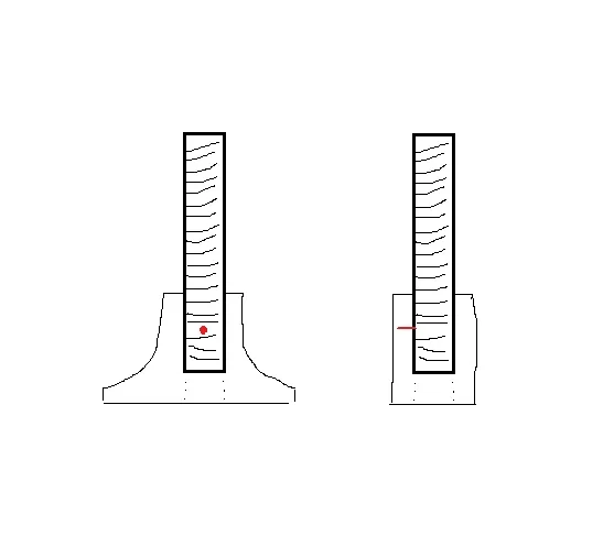
Bridge foot.webp
 
Gently remove wood from the North side of the pin, and from the South side of the pin...(above and below the pin in your diagram), with an Exacto Knife, (or small chisel) - just enough to expose the tip, and then grip the tip of the pin with a pair of small needle-nose pliers. (Try slightly twisting the pin, at first, to break it "free" it from its hole in the threaded shaft. Then pull it towards you.)
That's what I would try and do.
You can repair the small hole, and "chisel divots", with some wood filler to coverup your crime.
Good Luck.
 
Gently remove wood from the North side of the pin, and from the South side of the pin...(above and below the pin in your diagram), with an Exacto Knife, (or small chisel) - just enough to expose the tip, and then grip the tip of the pin with a pair of small needle-nose pliers. (Try slightly twisting the pin, at first, to break it "free" it from its hole in the threaded shaft. Then pull it towards you.)
That's what I would try and do.
You can repair the small hole, and "chisel divots", with some wood filler to coverup your crime.
Good Luck.
I was thinking small drill bits, North and South. I have variety packs from Ace Hardware.
 
  • Like
Reactions: 41 Hz
I don't know if they are available in a small enough size, but there is such a thing as a core drill bit, which is a hollow drill bit that drills around a core of material. If you can find one just slightly larger than the pin, you could literally drill the pin out in a core, then plug the hole by gluing in a thin hardwood dowel. In reading just now they are available in very small sizes.
 
I have spent a lot of time over the years, working with upright bass bridges.. I fit them frequently. I have sectioned many, and have installed adjuster wheels, and have experimented with different types of inserts. It sounds to me, that your real issue is the thread differences in the foot, and the new pickup threads.
Do you know what the threads are on the Yamahiko?
What I'd look into, is if you can re-tap the M8 insert to allow the new pickup's threads to work. This could also be done with a new insert of the correct threads, by step drilling the entire old insert out of the foot. This would be pretty risky, because the 'walls' of the foot are thin at the insert, and the heat generated by drill may be too much, unless you go slowly, in many passes. I have been very careful installing inserts, and still ended up with cracks forming in the foot. If this came to my shop, I'd duplicate the original foot with a new piece of quartersawn maple, and just drill and tap it for the Yamahiko. After the replacement, I'd re-fit the bridge to the top.
 
OP, could you take a picture of the actual bridge foot? My curiosity is asking how was the 1 mm pin installed in the larger pin? Is there a small hole in the side of the foot that the pin was pushed/pressed through?

My mechanic side is trying to wrap my mind around how it was assembled in the first place.
I'm guessing that the 1 mm pin is pushed through a small hole in the side of the foot (see illustration) and pressfit against the threads of the adjuster, making it difficult/impossible to rotate the threaded adjuster shaft??
Shrug??
My $0.03
 
I'm guessing that the 1 mm pin is pushed through a small hole in the side of the foot (see illustration) and pressfit against the threads of the adjuster, making it difficult/impossible to rotate the threaded adjuster shaft??
Shrug??
My $0.03
That makes sense. My thought was if it was a rolled pin, hollow, you might be able with a small drill bit on a slow setting catch the edge. Or could it be pushed through the a hole in the pin as well?

Got nothing going on today and this has me curious 🧐
 
  • Like
Reactions: Don Kasper
I'm guessing that the 1 mm pin is pushed through a small hole in the side of the foot (see illustration) and pressfit against the threads of the adjuster, making it difficult/impossible to rotate the threaded adjuster shaft??
Shrug??
My $0.03
I'd guess tiny hole drilled in bridge and through adjuster, pin driven in to pin it (no pun, that's its job as well as its name.) In that case the usual way to remove is to drive it through, but it sounds like the far end is not exposed, so that might not work here, and it might be assembled differently than I guess.
 
  • Like
Reactions: Don Kasper
I'd guess tiny hole drilled in bridge and through adjuster
I'll be surprised if this were the case...That would require a fairly sophisticated machining/drilling setup to execute. (Hand drilling would be very sloppy.)
IMFE, of course.
I hope the OP responds soon...the suspense is killin' me.
Thanks.
 
  • Like
Reactions: Dave Leighton
I'll be surprised if this were the case...That would require a fairly sophisticated machining/drilling setup to execute.
You mean something really fancy and hi tech? Like a drill press? (sorry I couldn’t resist)

This pin business is a bit of a head scratcher. If you can’t just loosen it and knock it out with a punch it’s likely more trouble than trying to save the bridge is worth.
 
  • Wow
Reactions: Don Kasper
You mean something really fancy and hi tech? Like a drill press? (sorry I couldn’t resist)
Not every knuckle head on TB/DB owns a drill press.(Sorry - I couldn't resist, and drilling out a steel pin with a drill bit could prove to be both tricky and messy.)
If you can’t just knock it out with a punch
You can't "knock it out...." because it is in a blind hole - not a thru-hole...(as I understand the OP's diagram. Sorry - I couldn't resist!)
Hey - we're all providing the OP with various options and suggestions - I can't wait to see what happens. TB at it's finest/craziest!)
Thx.
 
Not every knuckle head on TB/DB owns a drill press.(Sorry - I couldn't resist, and drilling out a steel pin with a drill bit could prove to be both tricky and messy.)

You can't "knock it out...." because it is in a blind hole - not a thru-hole...(as I understand the OP's diagram. Sorry - I couldn't resist!)
Hey - we're all providing the OP with various options and suggestions - I can't wait to see what happens. TB at it's finest/craziest!)
Thx.
Hey, I think you’re right! Bigger hammer then.
Or the hollow core bit that was suggested would do it. I’d probably just use an exacto semi judiciously to expose enough pin to get a grip it on then drill out the ugly whittling and fill the uniform hole.

Yes, curious to see what the word is from the guy who installed it.
 
  • Like
Reactions: Don Kasper