This is how I did the LEDs on my bolt on neck. Ive done the same on Neckthrough, its a bit more complex but its no biggie.
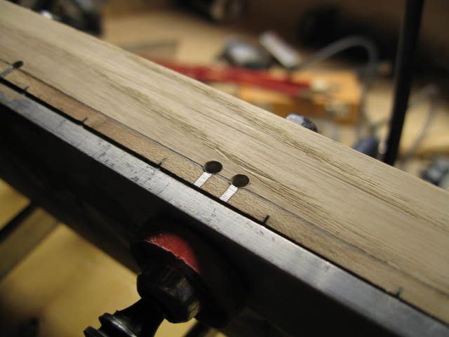
I started by dry-clamping my final tapered fingerboard onto my final tapered neck. Its good to be very descriptive. I used double sided tape and used my fingerboard to rout the edge of my neck. I inserted small aluminum strips as side dots and top dots. So the Leds are actually on the neck itself, a little different than the usual led system on a bass.
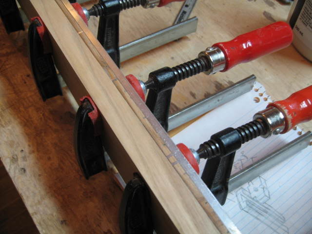
You really should use a fence to drill the holes but because of the clamps here I couldnt use one, but since most Leds should be in the fretboard (to replace the sidedots) then you should do it with a fence !! Keep the drill bit as short as possible to avoid having it wobble, check it on a test piece before.
I then routed out the channels for my truss rods. after doing so, I used the same fence and used my dremel with the attachment thingie to do 2 grooves.
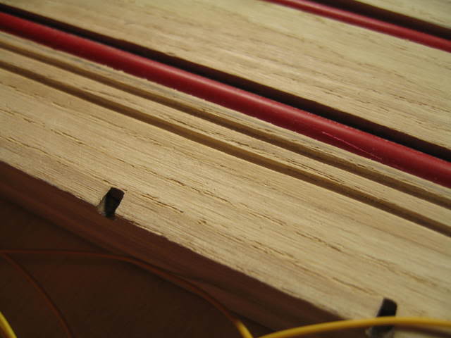
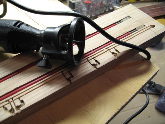
Alongside the 2 rod adjustment holes, I drilled a small hole for the 2 wires, I just used a handheld drill for this.
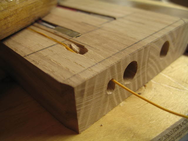
with the same dremel, attachment and bit, I routed out the 'cavities' for the resistances and leds and soulders.

I then tested every led with a resistance and a battery, there's only nine of them. Then I put Epoxy into the cavity and push the led into the hole. Feel free to go to the cornerstore and get a beer, or open up the fridge in your shop if you're that kind of fortunate lucky, lucky man... by then the epoxy should be dry.
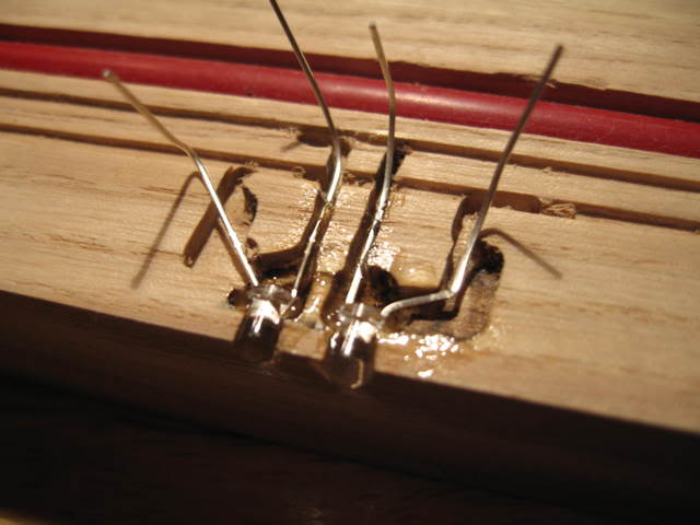
Very carefully I cut eveything and glue the resistances in with CA, soulder it all up there you go. I check them every led I do.
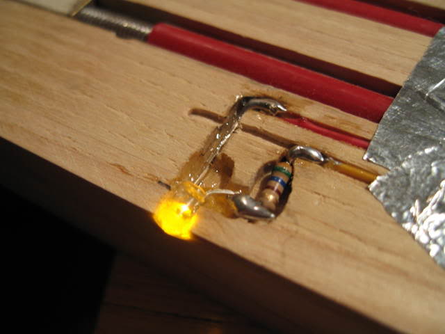
And here is the final thing.. not glued up but Ill show a pic when I get that done.
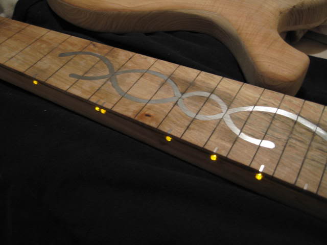
There is a certain 'law' which I forget the name of, that you must do depending on the amount of leds you put in the know what resistance ohm to use. If you have 30 leds instead of 10 and you use the same ohms they won't shine as bright. E=R*I, to avoid confusing you, I used 560ohms on this one, I had used 780 on another bass. They are only about 4cents each so buy a whole bunch of different ones to try em out. Hope im not forgeting anything and Ill be glad to answer questions, if asked. Peace
-Mario-
I started by dry-clamping my final tapered fingerboard onto my final tapered neck. Its good to be very descriptive. I used double sided tape and used my fingerboard to rout the edge of my neck. I inserted small aluminum strips as side dots and top dots. So the Leds are actually on the neck itself, a little different than the usual led system on a bass.
You really should use a fence to drill the holes but because of the clamps here I couldnt use one, but since most Leds should be in the fretboard (to replace the sidedots) then you should do it with a fence !! Keep the drill bit as short as possible to avoid having it wobble, check it on a test piece before.
I then routed out the channels for my truss rods. after doing so, I used the same fence and used my dremel with the attachment thingie to do 2 grooves.
Alongside the 2 rod adjustment holes, I drilled a small hole for the 2 wires, I just used a handheld drill for this.
with the same dremel, attachment and bit, I routed out the 'cavities' for the resistances and leds and soulders.
I then tested every led with a resistance and a battery, there's only nine of them. Then I put Epoxy into the cavity and push the led into the hole. Feel free to go to the cornerstore and get a beer, or open up the fridge in your shop if you're that kind of fortunate lucky, lucky man... by then the epoxy should be dry.
Very carefully I cut eveything and glue the resistances in with CA, soulder it all up there you go. I check them every led I do.
And here is the final thing.. not glued up but Ill show a pic when I get that done.
There is a certain 'law' which I forget the name of, that you must do depending on the amount of leds you put in the know what resistance ohm to use. If you have 30 leds instead of 10 and you use the same ohms they won't shine as bright. E=R*I, to avoid confusing you, I used 560ohms on this one, I had used 780 on another bass. They are only about 4cents each so buy a whole bunch of different ones to try em out. Hope im not forgeting anything and Ill be glad to answer questions, if asked. Peace
-Mario-