
Enjoy the benefits of a premium membership!
Upgrade Account
-
TalkBass has been independent since 1998. Add your voice.
Create a free account to reply to discussions, view embedded media, and browse with fewer display ads.
Join free Log in
Want zero display ads or expanded classifieds tools? Compare plans.
You are using an out of date browser. It may not display this or other websites correctly.
You should upgrade or use an alternative browser.
You should upgrade or use an alternative browser.
Three pickup bass parallel/series switch
- Thread starter Amalgam
- Start date
More options
Who Replied?
If you are looking at flipping phase on, probably, the middle pickup (like a strat) then this may help
Mod Garage: Adding an Out-of-Phase Switch to a Telecaster
Mod Garage: Adding an Out-of-Phase Switch to a Telecaster

If you are looking at flipping phase on, probably, the middle pickup (like a strat) then this may help
Mod Garage: Adding an Out-of-Phase Switch to a Telecaster
OP asked about series/parallel, not phase.

Two pickup basses require at least four poles to do this right?
Is that keeping a volume control for each pickup in both modes? I've been sick and mostly bedridden this holiday and looked at this again I think I did it with three poles, if my fevered head didn't betray me LOL.
This is embarrassing, but I think I already got it, but I hadn't thought it through as I thought it was preliminary work that I was stuck on.
The series mode might look weird, but that's because it's supposed to be series mode with individual volumes whin series mode.
I think I figured it out before I posted this, but didn't know because it was a preliminary guess that I assumed was wrong. Basically, both of pickups on the sides (non middle) would only need one pole because the ground of one pickup can be shared in both parallel and series mode, and the output of the other can be shared as well.
There could be another way, but this way is pretty straightforward.
I didn't post this because I have yet to fix my individual volume control in series mode wiring diagram yet.
The series mode might look weird, but that's because it's supposed to be series mode with individual volumes whin series mode.
Yes, a volume control per pickup in both modes.Is that keeping a volume control for each pickup in both modes? I've been sick and mostly bedridden this holiday and looked at this again I think I did it with three poles, if my fevered head didn't betray me LOL.
I think I figured it out before I posted this, but didn't know because it was a preliminary guess that I assumed was wrong. Basically, both of pickups on the sides (non middle) would only need one pole because the ground of one pickup can be shared in both parallel and series mode, and the output of the other can be shared as well.
There could be another way, but this way is pretty straightforward.
I didn't post this because I have yet to fix my individual volume control in series mode wiring diagram yet.
Very cool you're working on that. Translating a schematic into a wiring diagram is a good ability to have.I have yet to fix my individual volume control in series mode wiring diagram yet.
So, riffing off the three pickup schematic you're working on, it looks possible with 5 poles.Is it possible to use a toggle switch with less than six poles to switch between parallel and series mode on a three pickup bass?
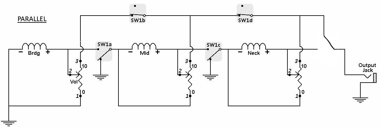
From the 3 pickup schematic, the green dots show where all sets of contacts (poles) should go for series/parallel switching. The following circuit doesn't represent anything, but was only an idea scratch pad for me.:
In Series mode, the bottom 3 dots would provide continuity between all pickups to the output jack. The top 2 dots would be open.
In Parallel, the bottom left 2 now connect to system ground, allowing Mid and Neck pickup independant system operation. The top 2 are closed, allowing all three modules to sum together as one signal. The bottom far right diverts the three summed signals to the output jack.
I don't have better schematics drawn up for the three pickup circuits yet.
Good observation. I even tried that when working this up. Then had my hopes dashed on the rocks far, far below LOL.If you look at the image from just left to right, couldn't you remove the last pole, knowing that the current in the extra wire wouldn't interact with any extra parts in series, and come into play when in parallel?
You're right that in series, it's no issue. However, in parallel, if I dialed the neck pickup to 0, the combined signals get sent to ground thru the Neck pickup ground. The Neck pot would be like a master volume. This scratch schematic is redrawn in parallel and Neck volume at 0. Green dots are pole locations, yellow where the 5th pole was.:
Here's a clean version in parallel. Notice the 5th pole switch contacts prevent the combined sigs from getting to the Neck volume pot wiper arm.:
Here's the series circuit:
This change wouldn't work for both modes? I was under the impression that there's only one output needed from series mode originally, but it looks like that could be wrong. I did imagine that parallel and series mode could share the same section to the output, and I'm not quite sure why that couldn't be true.
If it needs five poles, I might have to add a tiny bit of a circuit depending on switch position as I don't know of any five pole toggle switches, and the only six pole is extremely large and only lasts 5,000 cycles.
If it needs five poles, I might have to add a tiny bit of a circuit depending on switch position as I don't know of any five pole toggle switches, and the only six pole is extremely large and only lasts 5,000 cycles.
Last edited:
This change wouldn't work for both modes?
You want to keep the permanent connection like you've drawn in the schematic for both series and parallel?
If yes, then parallel will work as expected. In series, the Neck volume control won't be independent anymore, but becomes a master volume. :
If no, then I'm not sure what you're asking.

So I know that this was posted quite some time ago, and I've given in and given up on this so many times now, but I was hoping that you could look at this again for me. What I'm wondering is what would happen if I had the parallel and series signals separately go to a two channel buffer/mixer at the end? Both signals would get sucked in, which wouldn't matter if I was sticking to the system only being in parallel or series, but I've started thinking about having two four pole switches that are master parallel/series switches that are located between pickups 1 and 2, and, 2 and 3. I could easily add the "fifth" pole to the second switch... Or I could try adding series out of phase to each of those switches, and use a buffer/mixer to do the rest... I just don't know how it'd affect that vulnerable "fifth" pole how it's shown above.Sorry, man. Hopefully someone else has another solution.
I've been wondering about using a buffer anyway if there are two signal paths before the preamp stage anyway.
Also, apologies for editing your image... Um, it looks nice.. and was easy. I'll attach the original edits below.

Last edited:

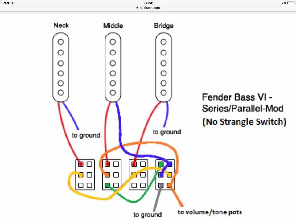
This is how I wired my Bass VI using the factory DPDT switches already present, however 3 SPDT and one DPDT would do it. The only series options are B+M and N+M, but those two combinations sound great in series. B+M in series has a sort of Sterling Ball kind of punch, N+M in series is sort of a Mudbucker type experience.
No problem, I'm glad you're using them. Helps me out 'cause I'm already familiar with that format.Also, apologies for editing your image...
Regarding the thumbnail you attached with the 4 circuits. Disregard the bottom two schematics. Mixing series and parallel sections at once throws in all sorts of control issues that aren't consistent or intuitive.:
I liked that idea, so I sketched it out and put a dual preamp/buffer just before the output jack (I think that's where you suggested it). This replaces the 5th set of contacts and leaves just 4.What I'm wondering is what would happen if I had the parallel and series signals separately go to a two channel buffer/mixer at the end? Both signals would get sucked in, which wouldn't matter if I was sticking to the system only being in parallel or series...
You're right, the neck volume pot would feed both preamp inputs at the same time regardless of series or parallel selection. I think 2 more sets of contacts would be needed for proper isolation. The 2 extra's would be located just before each amp input. No way to tell if that simultaneous feed would be good or bad unless prototyped and tested.
Any phase reversals should be tested first during prototyping as you may, or may not, like it what you hear.
If you have all the parts, start throwing stuff together to see what ideas you wanna keep, what you wanna discard. Just my suggestion based on how I'd do it.
You have alot of ideas. Gotta figure out a test setup so you can quickly test those ideas. Much faster than waiting for someone to answer in the forum.


