• TalkBass has been independent since 1998. Add your voice.
    Create a free account to reply to discussions, view embedded media, and browse with fewer display ads.
    Join freeLog in
    Want zero display ads or expanded classifieds tools? Compare plans.

Would these work for a rotary selector for 2 pick ups?

Hi all,

Im looking at putting in a rotary switch into couple my basses so i can get bridge-bridge/neck parallel-bridge/neck series-neck. So im looking for a 4 position rotary switch. These are the closest i have found online to purchase. Would this work for my needs ?

Thanks for any help/advice
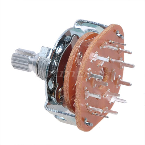
s-l500.jpg
 
By counting the pins I would say its a 2-pole 6-way rotary switch. They usually have a configurable stop, so you can set it up as a 2-pole 4-way, which is what you want. You could wire it as follows to get the four configurations you're after:

Rotary_sw.jpg

Sorry for the diagram quality - I knocked it up in a hurry.

In position 1 the bridge pup is connected to the output and the even though the neck pup is also connected, the other side is floating so it won't contribute anything and you get just bridge. Position 2 is the same as position 1 except the other end of the neck pup is grounded, so you get both pups in parallel. In position 3 one side of the neck pup is connected to the bridge pup output so you get them both in series, and in position 4 one side of the neck pup is grounded and the bridge pup is unconnected, so you get just the neck.

I'm assuming you don't want individual volume/tone controls as that would complicate things somewhat. If you want a master volume and/or tone control just connect them at the output of this circuit before the output jack.

I hope this helps.
 
By counting the pins I would say its a 2-pole 6-way rotary switch. They usually have a configurable stop, so you can set it up as a 2-pole 4-way, which is what you want. You could wire it as follows to get the four configurations you're after:

View attachment 3700730
Sorry for the diagram quality - I knocked it up in a hurry.

In position 1 the bridge pup is connected to the output and the even though the neck pup is also connected, the other side is floating so it won't contribute anything and you get just bridge. Position 2 is the same as position 1 except the other end of the neck pup is grounded, so you get both pups in parallel. In position 3 one side of the neck pup is connected to the bridge pup output so you get them both in series, and in position 4 one side of the neck pup is grounded and the bridge pup is unconnected, so you get just the neck.

I'm assuming you don't want individual volume/tone controls as that would complicate things somewhat. If you want a master volume and/or tone control just connect them at the output of this circuit before the output jack.

I hope this helps.

Thanks for the quick response, the pic i post is of a 3 pole 4 way. Howd i know if a 2 pole 6 way has the configurable stop? and thank you for the diagram. the output of the rotary would go to a active passive push/push on the master volume then to the onboard eq.
 
Oh yes if I squint I can see the third terminal in the middle - that would make it a 3-pole 4-way, so no configurable stop is needed. Connecting the output to your push/push master volume and onboard eq will work.
With 3 poles we can improve the circuit a bit so that the neck pickup isn't left connected in position 1, which isn't ideal for noise pickup but was necessary if there were only 2 poles.
Rotary_sw2.jpg
 
Oh yes if I squint I can see the third terminal in the middle - that would make it a 3-pole 4-way, so no configurable stop is needed. Connecting the output to your push/push master volume and onboard eq will work.
With 3 poles we can improve the circuit a bit so that the neck pickup isn't left connected in position 1, which isn't ideal for noise pickup but was necessary if there were only 2 poles.
View attachment 3700788

Hi @Glyn - Can you say more about the noise that might occur when using a 2 pole four position switch? I'd really like to use Link Removed for space reasons and it's 2p4t.

The squiggly line near the words Neck and Bridge in your diagram, are you representing the pickups' coil, or is there another component that should be there like a resistor...

Also - I'm planning to use your diagram to wire a single Bartolini 2J Squared pickup for north coil, series, parallel, south coil operation. Any reason that won't work?

Lastly, I notice that your diagram results in position 1 being bridge position. Position 1 would be the knob turned clockwise toward the neck... is that correct? If I wanted the knob's physical rotation to "point" towards the selected orientation I would just reverse the 1,2,3,4 numbering on each side, yes?

Thank you!
 
Last edited: