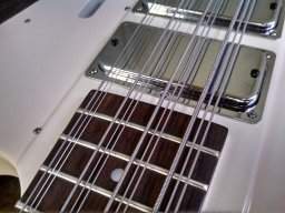
Does anyone out there have good instructions to add the series / parallel / single coil 3 way selector switch to a traditional single humbucker 2 band stingray? Pretty much like a stingray 5 set up..
Thanks!
Thanks!

TalkBass has been independent since 1998. Add your voice.
Create a free account to reply to discussions, view embedded media, and browse with fewer display ads.
Join free Log in
Want zero display ads or expanded classifieds tools? Compare plans.


Did you want to use a 3 way Strat/Tele style blade switch or a mini toggle?
Blade switch:
[Invalid or Expired Link Removed]
Mini toggle:
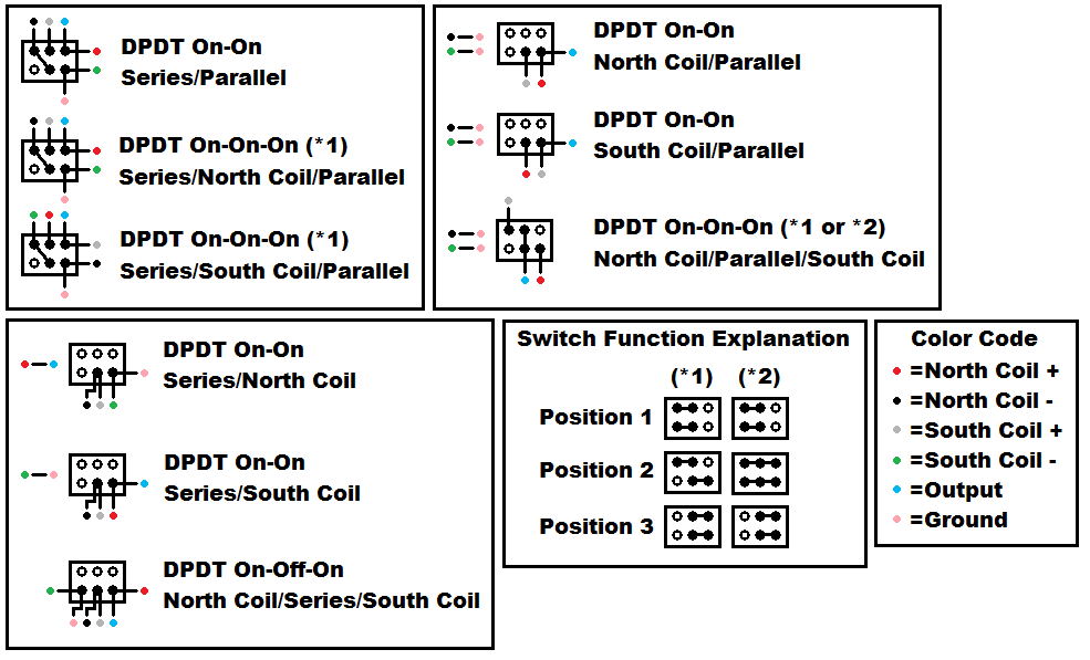
Did you want to use a 3 way Strat/Tele style blade switch or a mini toggle?
Blade switch:
[Invalid or Expired Link Removed]
Mini toggle:
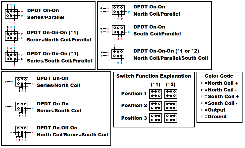
I'm assuming that north coil is the neck coil and south coil is the bridge?
Thanks again!!!
Probably a mini toggle. Thanks a bunch! Looks like the MM stock pickup is a 2 wire pickup. I'm assuming that each coil will need its' own two wires.. so essentially 4 wires will be coming off of the two coils right?
Does your bass have two pickups?
I'm assuming that north coil is the neck coil and south coil is the bridge?
Thanks again!!!
Line6man,
I'm going to go with the North Coil/parallel/south coil config. A couple of questions..
1. The north coil i assume is the coil closest to the neck, the south being closest to the bridge right?
2. Also, on the diagram for this configuration i get the 6 poles on the back of the switch are represented by the box, what locations are the two horizontal lines next to the box where you solder nc- , sc- and the grounds?
Thanks for bearing with me!
BTW this is for a single humbucker stingray.

1. Yes.
2. The lines are to indicate that the - phase connection of each coil connects to ground. Perhaps I should have used a ground symbol there.

Line6man,
I'm going to go with the North Coil/parallel/south coil config. A couple of questions..
1. The north coil i assume is the coil closest to the neck, the south being closest to the bridge right?
2. Also, on the diagram for this configuration i get the 6 poles on the back of the switch are represented by the box, what locations are the two horizontal lines next to the box where you solder nc- , sc- and the grounds?
Thanks for bearing with me!
BTW this is for a single humbucker stingray.


The stock MM pickup (at least on my 2004 SUB5) is two open coils wired together in parallel at the pickup assembly with only two wires brought out from the pickup assembly to the preamp. It *is* possible to separate the two coils and run two additional wires to the preamp, I've done it, but if you're not EXTREMELY careful (and know what you're doing) it would be VERY easy to burn up part of the pickup winding while unsoldering the tiny wires and end up with a dead coil.
On my SUB5, the additional wires had to be 22 gauge or smaller to fit thru the tunnel to the preamp compartment. I used a DPDT mini toggle switch between the bass and treble controls. The two electrolytic power caps on the 9v voltage divider will need to be replaced with equivalent tantalums to have sufficient mechanical clearance for the switch.
Now, there's a trick you can pull with the typical three-way coil switch so as to put a series resistor between the coils in the series selection only. If you use a 180 Kohm resistor, you'll get level matching between the parallel/single-coil options and the series option. I had to determine that empirically by trial and error. This value is surprisingly sensitive, even 1% difference makes an audible level difference.
Unfortunately, with the series coil connection the pickup presents a very high impedence to the preamp, approximately twice what the preamp would like to see. Have you ever plugged a passive bass into a amplifier (or amplifier channel) that was designed for the piezo output on an acoustic guitar? The sound has enough bass, plenty of highs, but sounds 'tight' in a way that is hard to describe but easily audible? It sounds like that. To an electrical engineer, the damping is mismatched. Now the way to solve that is to add a series/parallel impedance-matching resistor network to the series option only. If you've worked in electronics and are familiar with Thevenin's theorem and how to calculate a Thevenin equivalent, it isn't that hard. I don't know how to explain it in words without resorting to Thevenin's though. A schematic would show what I'm talking about. Unfortunatley, my only schematic capture program these days yields drawings that are far too large for TB, I've tried.
You can add a push-pull switch to the volume control, but you'll have to clip off the corner of the circuit board to do so. There aren't any traces right there though so it's doable. I put a push-pull mute switch on mine because I do some hand & mallet percussion and like to be able to drop mallets and get back to playing bass quickly.
Here's pics of the SUB5 that has this mod (also dimpled the knobs):
SUB5_Bass by BokononBass
Just the control plate:
Control plate
I wish I'd taken some pictures of the modification, but didn't think about it at the time, sorry.
Best of luck!!!!!!!!

This is an interesting idea. So you're saying to run the 180 Kohm resistor across the two terminals of the switch that connect the "hot" of one coil to the "ground" of the next? Or in addition to a regular jumper connection? I just installed two switches on my stingray. A 2 way and 3 way switch. So now I can get either coil alone, or parallel/series. Of course, series is way louder than all the other options and I wouldn't mind taming it.
You might want to bear in mind that this thread is over five years old, and the person you quoted was last seen here nearly two years ago.
Otto


