• TalkBass has been independent since 1998. Add your voice.
    Create a free account to reply to discussions, view embedded media, and browse with fewer display ads.
    Join freeLog in
    Want zero display ads or expanded classifieds tools? Compare plans.

25" short scale V2.0

This build is about a year old, but i forgot to do a build log... :oops:

The bass was built as a first christmas present last year for my nephew. I did the same a few years ago for my niece. Build log for that build here. The shape is more or less the same, but with a different wood selection and a few design tweaks.

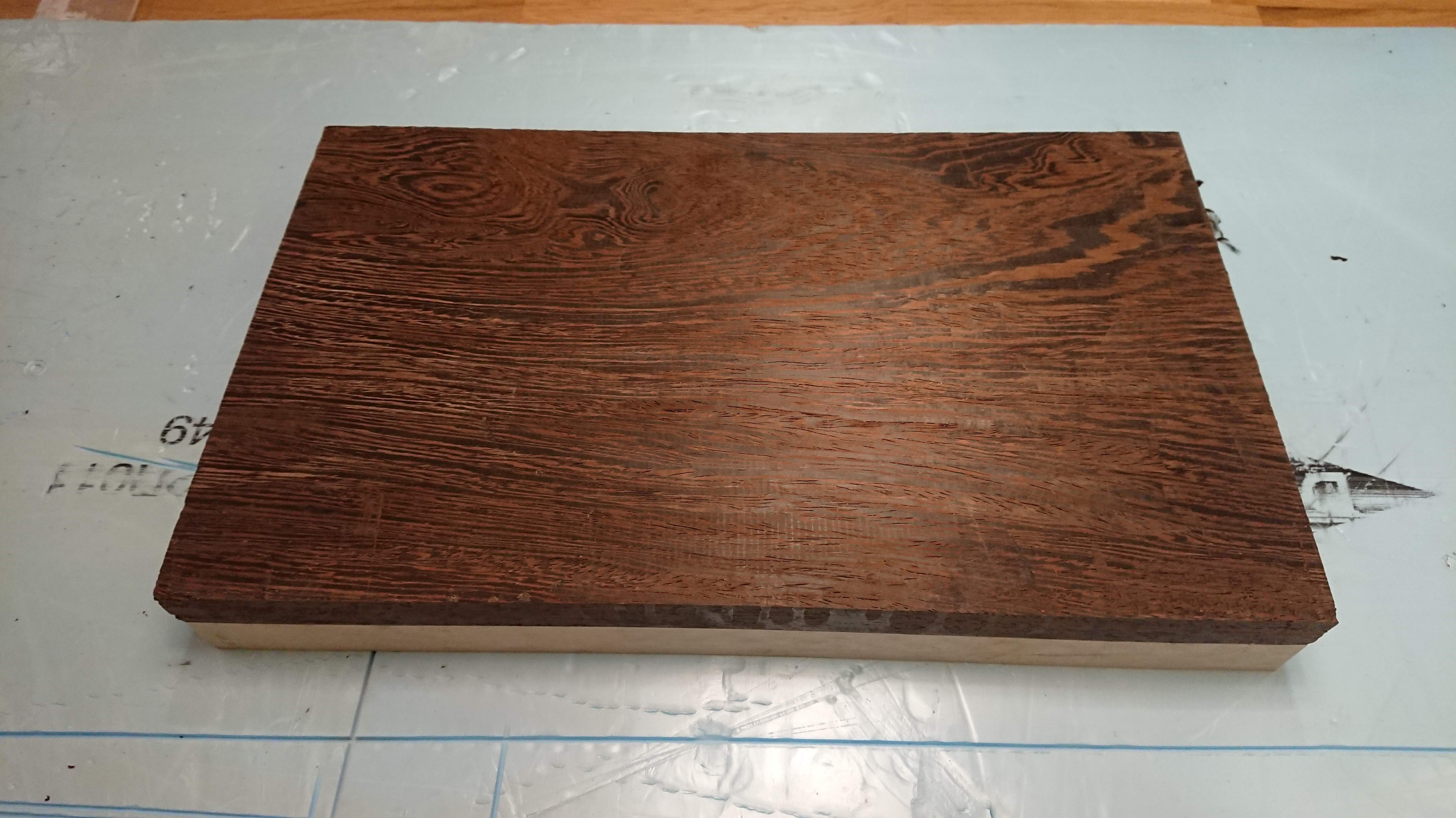
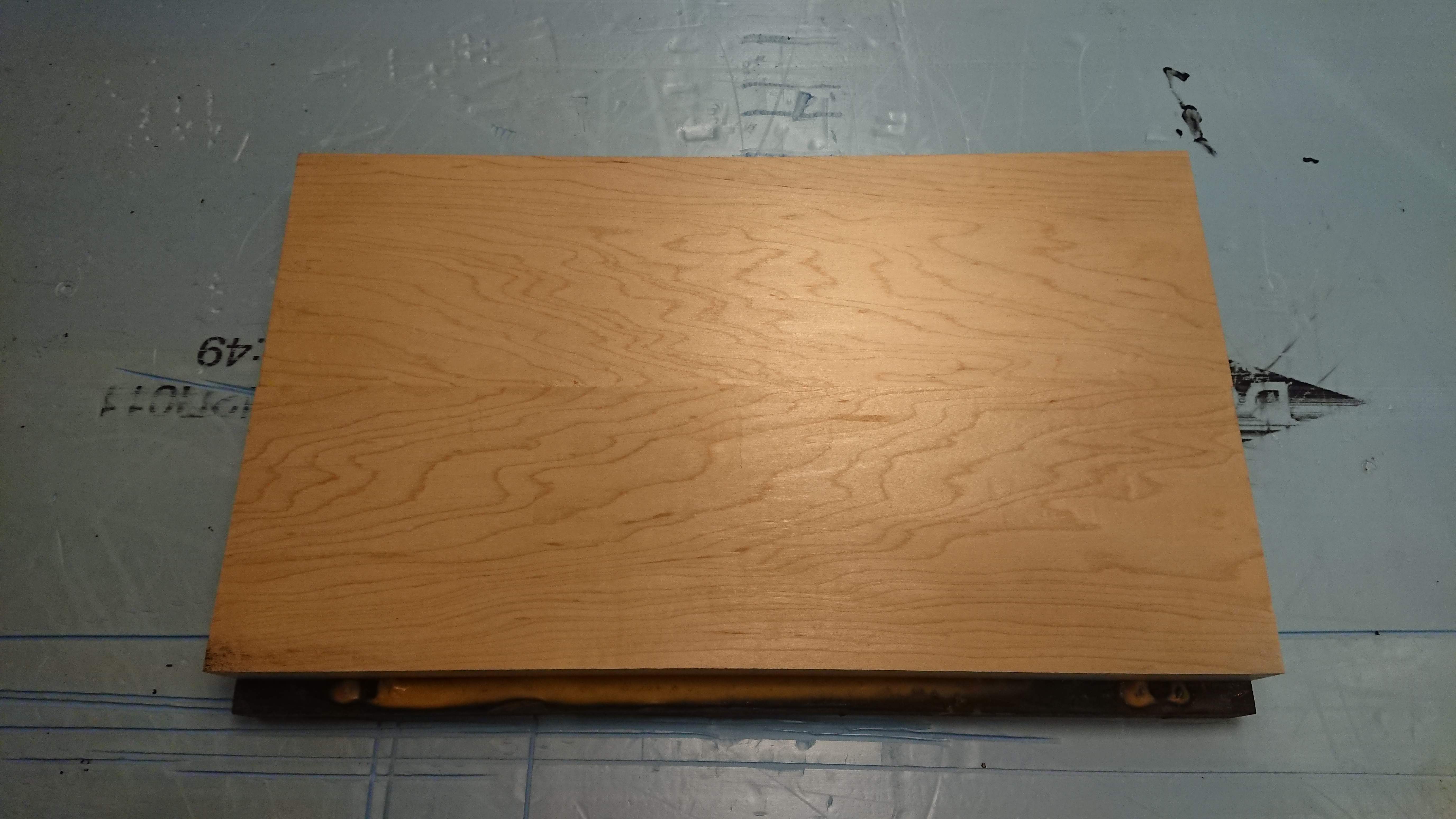
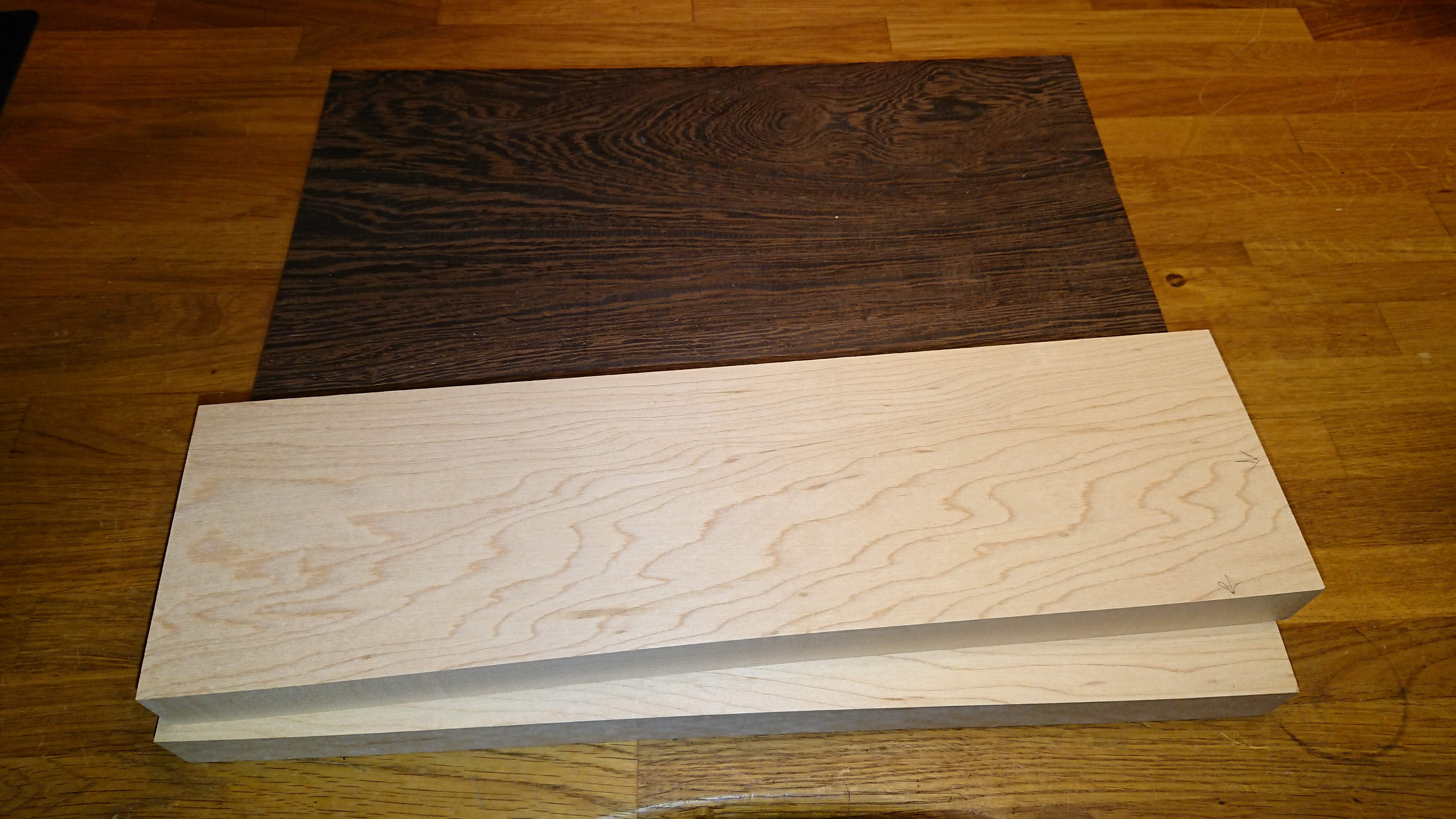
The body will be one piece wenge on the front and two piece maple on the back. The pieces are a bit too thick, but I figured it was time to use up some old stock. The maple is originally a neck beam, but the grain was nice enough for a body. :)
DSC_1353.JPG


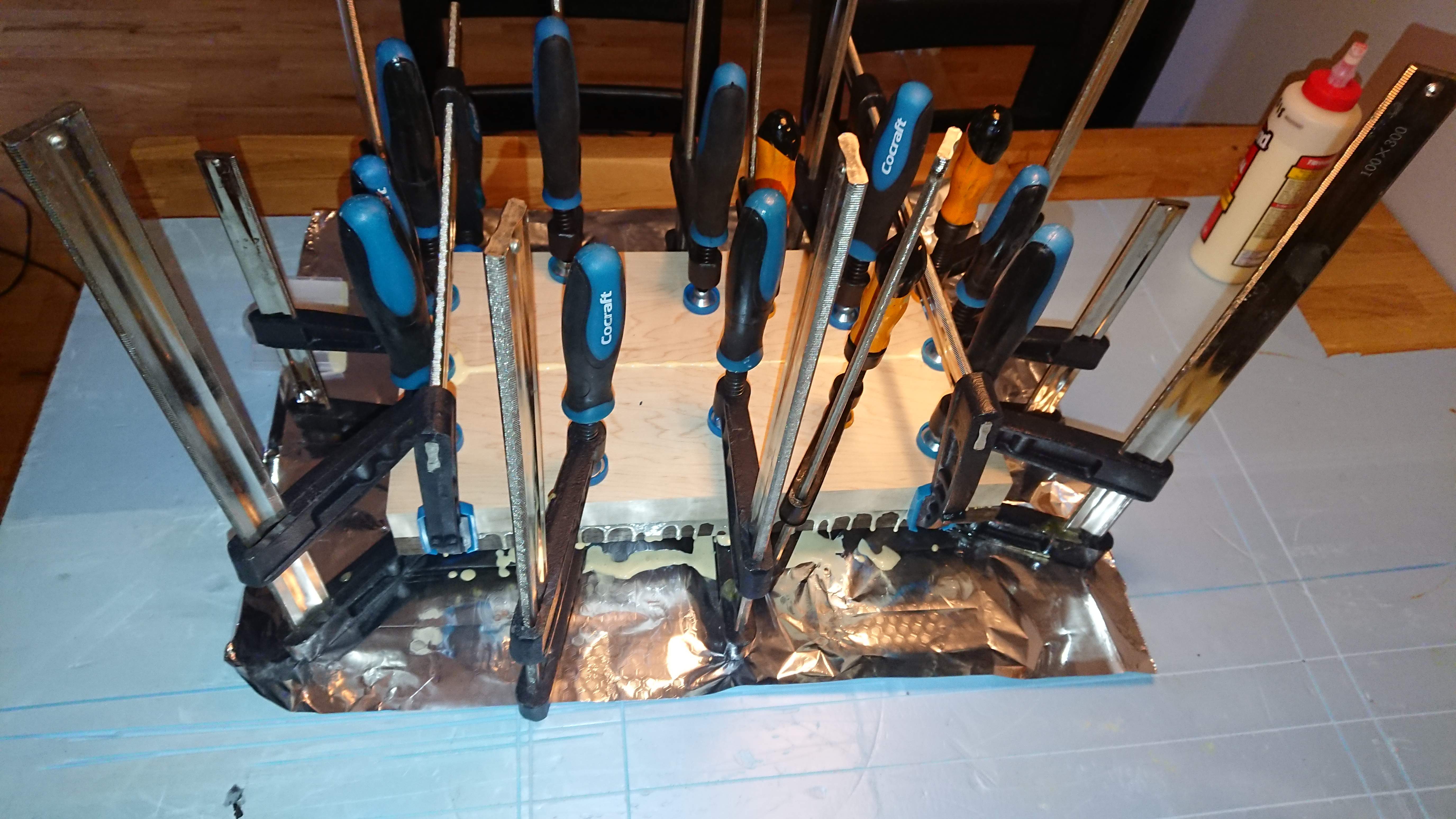
All glued and clamped. I glued all three pieces in one go. This was the easiest solution to keep everything aligned.
DSC_1355.JPG


All glued up!
DSC_1357.JPG

DSC_1358.JPG


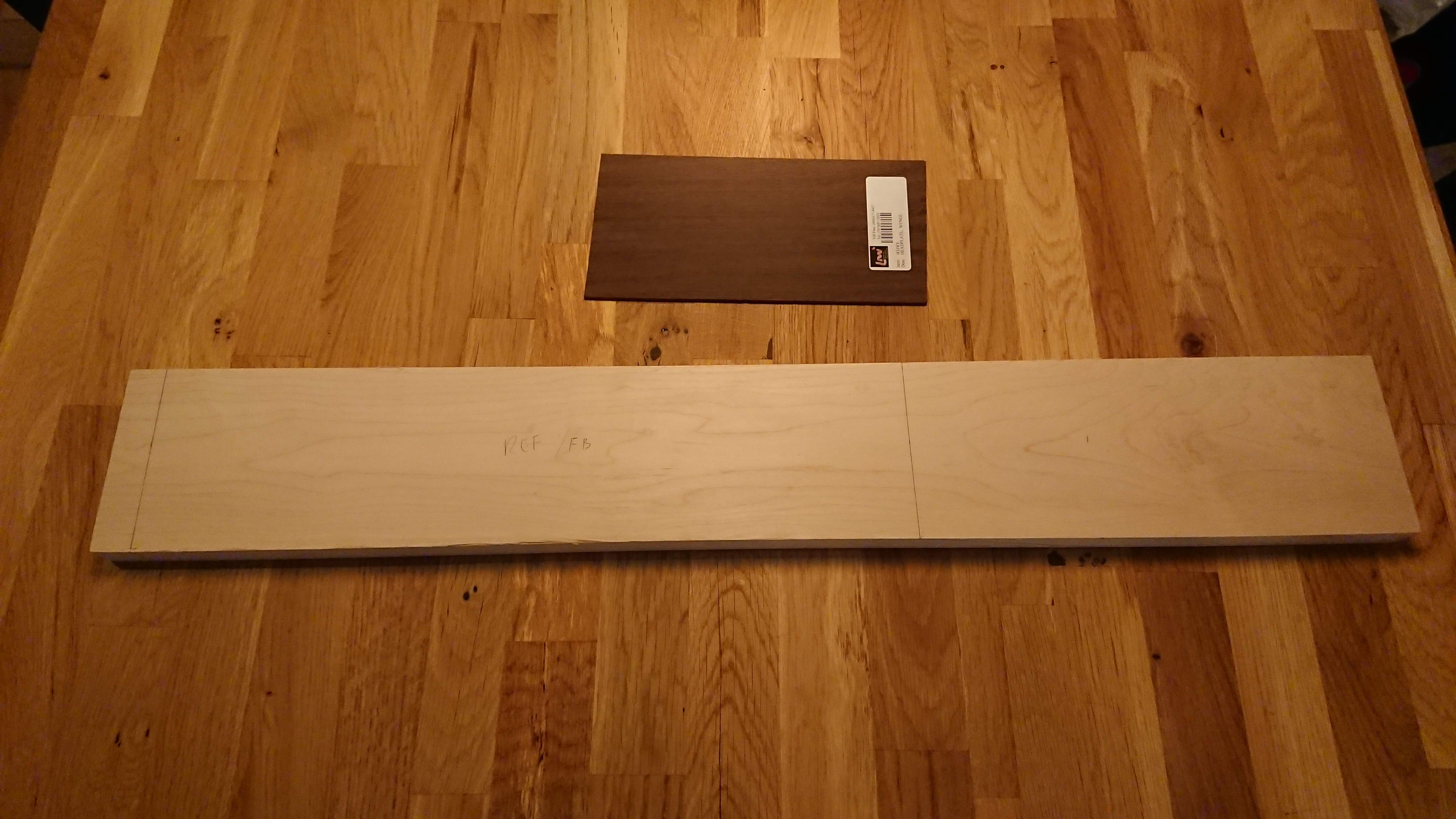
Woods for the neck. I have no idea why I had two maple neck blanks laying around, but at least I found a use for them now. :)
DSC_1359.JPG


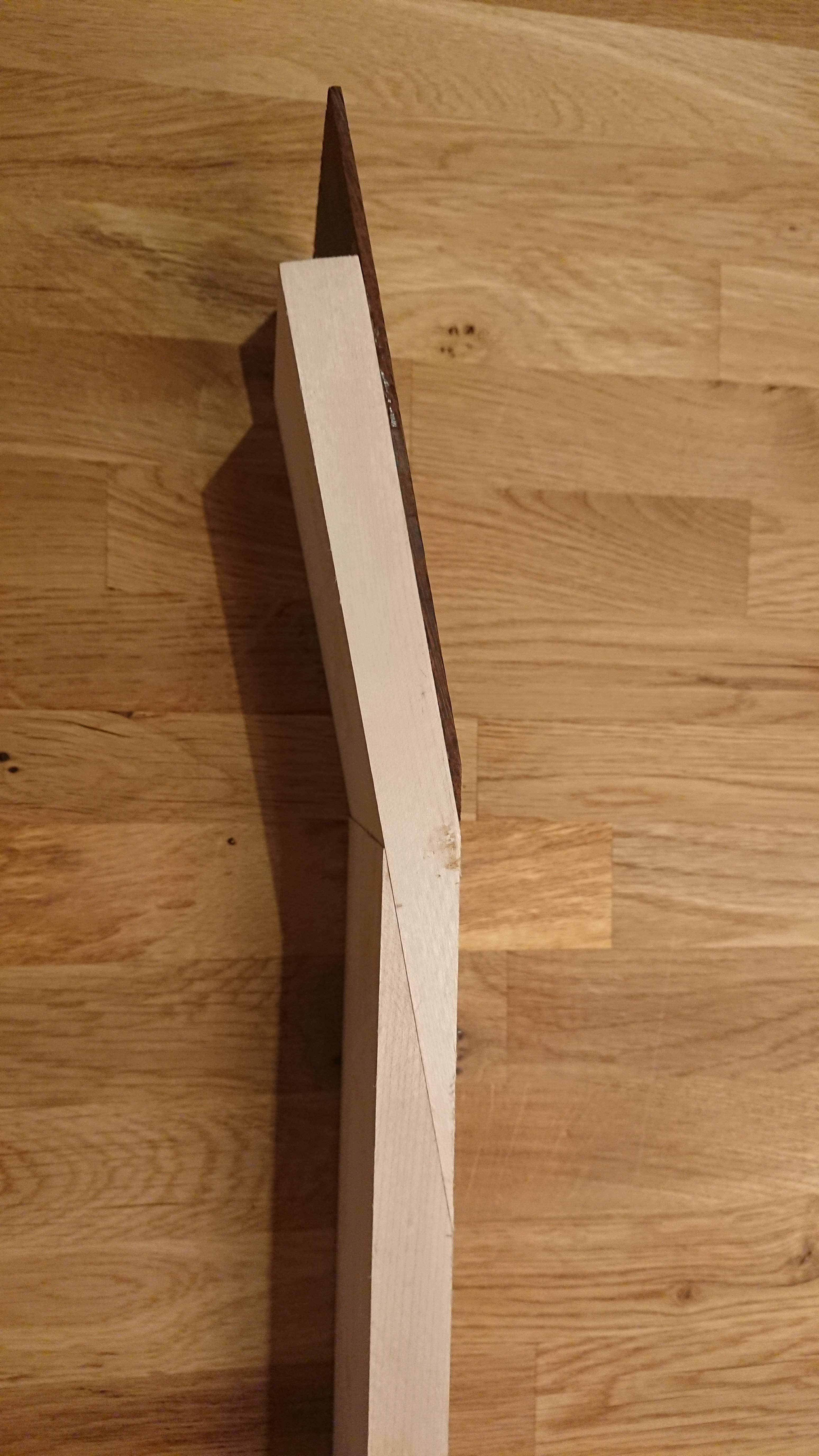
Scarf joint sawn by hand. later it was adjusted with a hand plane.
DSC_1361.JPG


Front plate glued on.
DSC_1362.JPG

DSC_1363.JPG


More to come...
 
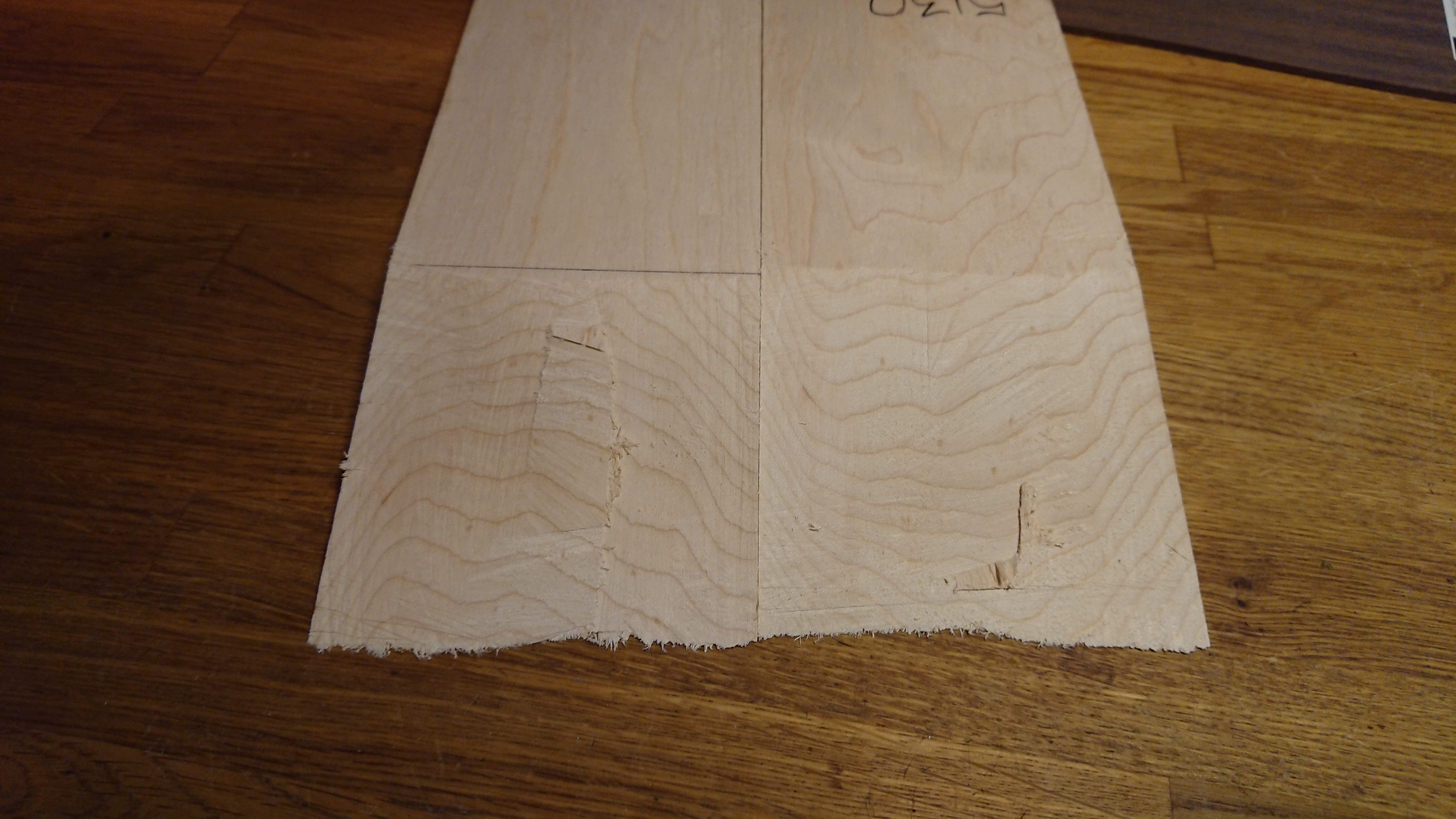
After the front of the headstock was planed it was time to cut out the headstock shape. The lines on the back are there to align the shape with the angle of the scarf joint.
DSC_1380.JPG


Shape cut out. I also did a manual run to take down the thickness of the headstock to save a lot of work later. I really need to sharpen that router bit... :jawdrop: Those lines are from the frame of the CNC router flexing. Not a good thing...
DSC_1381.JPG


A bit nicer from the front. As you can see although the headstock won't separate from the waste stock I still used tabs. This was to prevent the risk of flexing that could pinch the router bit. The bit is thin and run at a long shank. Any pinching will induce chatter and could break the bit. The cut still won't be pretty, but that will get cleaned up later.
DSC_1382.JPG


As it turns out I did miscalculate something back when i cut the scarf joint. There was supposed to be about 1cm of clearance. Turns out the clearance was less than the diameter of the router bit... (3mm) Oops! :whistle:
DSC_1383.JPG

Waste stock removed. Dry run before glueup. Toothpicks was used to align and prevent slipping.
DSC_1386.JPG

Glue and cleanup done! You can just about make out the slight curve in the glue line. This was to keep as much pressure as possible on to the part that will be a part of the neck.
DSC_1387.JPG

Neck back in the CNC to be cut to shape. Center line and reference points marked to make sure that I hit the existing cuts on the headstock.
DSC_1404.JPG

Done!
DSC_1409.JPG

The cut stopped slightly shy of the headstock. This was to prevent overshooting the cut on the bottom of the neck as the existing cut was at an angle. I could fix this in software, but it's not worth the hassle.
DSC_1410.JPG

Tabs was used on the neck for the same reasons as on the headstock. There was also some material left in the scarf joint. This is because the bit wasn't long enough.
DSC_1412.JPG

Neck free from the waste stock! The transition was cleaned up later when the neck was shaped.
DSC_1413.JPG

I also had an ebony fretboard blank laying around. It had twisted ever so slightly over the years, so I had to mill it flat. The board was clamped down without straightening out the twist and then a rectangle was milled to make a flat reference surface. The board was then flipped and the same process repeated before cutting out the shape.
DSC_1415.JPG

Inlays and fret slots was cut in the same operation. As you can probably see I messed up the alignment on the fret slots. Luckily I caught the mistake quickly enough that the line that was milled wrong was shallow enough to be sanded out later.
DSC_1417.JPG

Dry fit of the fretboard. You can also see the fretboard inlays cut in some thin 6mm maple scraps.
DSC_1421.JPG

Fretboard glued to the neck. Another forest of clamps. :)
DSC_1425.JPG
 
The next step was to shape the body. The stock used for the body was way too thick. Since I didn't have a planer i used the CNC router to mill down the thickness. That's a decent chunk of wenge turned to dust...:eek: That's about an hour and a half of milling time. I didn't bother running the vacuum. I did keep a very close eye on it though. If anything had got very hot there could be a risk of fire. I did discover at the end that the coolant pump had stopped working. :eek:
DSC_1426.JPG

The top had to be milled flat and cut without moving anything to keep the reference points in the correct place. I had to get a bit creative with the clamping.
DSC_1428.JPG

The neck pocket pokes though to the maple layer. This makes some tasty looking chips. :woot:
DSC_1430.JPG

Most of the cutouts done. The edges was cut first with a small bit first to prevent tearout.
DSC_1431.JPG

Front cutout done. The upper left hole was one of four registration holes used to align the blank for the rear cuts. As you can see I did make a mistake here. When I created the toolpath for the cutout I set the cut to the inside of the line, not the outside. :eek: Luckily I caught it more or less in time to be fixable. I just increased the roundover diameter a step.
DSC_1433.JPG

Routing of the back. I also reduced the thickness here, but only in the area of the body. This was to cut down on machine time. This is the last step before waste removal anyway. The electronics cavity is pretty deep, so I had to run the bit on a long shank again.
DSC_1434.JPG

Aaaand done! Well, almost...
DSC_1435.JPG
DSC_1437.JPG
 
Now that the rough shaping is done it's time for the fun part. Detail work. :)

First up was gluing in the fret markers. I masked off the fretboard to prevent too much glue on the fretboard that would make cleanup more difficult.
DSC_1441.JPG

Ready for radius sanding.
DSC_1442.JPG

The groove around the body was cut to hold a strip of purfling. I had some large pieces of white and black veneer to make some (relatively) wide strips.
DSC_1444.JPG

To save the hassle of hot bending the strips I shaped them during gluing. Since the purfling was slightly thinner than the cutter I used to shape the body I could use the body and waste stuck as a caul. The gluing was done in three sections. I lined the caul with tape, added some glue and pushed the purfling into the gap. The screwdriver on the left was used as a clamp as there wasn't any space to fit a proper clamp. The edge of the body would get a roundover later anyway, so denting the body wasn't a problem.
DSC_1446.JPG

DSC_1449.JPG

Purfling after shaping. Keen observers may have noticed that the shape doesn't quite match the groove. The shape was slightly too big, but is was close enough. I stuck the strip into the groove before the glue was fully dry which made the strip pretty flexible.
DSC_1450.JPG

Shaping done, ready for glue. The overhang into the neck pocket was left until after gluing to make the ends match the body perfectly.
DSC_1451.JPG

Skunk shavings! :woot:
DSC_1456.JPG

All glued in place and shaven down close. The entire top was sanded properly later.
DSC_1457.JPG

The truss rod cover, or rather fretboard extension, was glued in place. I was careful to mask the headstock from gle, as the cleanup of glue here would be a pain.
DSC_1459.JPG

End result. The curve is roughly shaped here. It was thinned down a bit later to make better room for strings.
DSC_1460.JPG
 
What are you going to do for strings?

Since you asked, let's jump a bit forward in time. :)


The strings I'm using are the lower 4 strings from a 5 string set. I can't remember exact type but I think they were Fender strings.

The D and G strings are thin enough to be able to wrap around the tuner posts, but the E and A have to be thinned down. This means removing the outer layer of wrapping from the end of the string. There is a risk of the string unraveling when doing this. To reduce the risk I first wrap the string in tape just below where i have to unwind. I then clamp the string tightly in a small vice. The vice have a V-groove in the jaws that hold the string nicely. I then unwind the string and cut off the excess and clamp the loose end as close to the string as I can.
DSC_1581.JPG


I have done this on two basses now and none of the four strings have unwound. Maybe I'm just lucky.
 
Since you asked, let's jump a bit forward in time. :)


The strings I'm using are the lower 4 strings from a 5 string set. I can't remember exact type but I think they were Fender strings.

The D and G strings are thin enough to be able to wrap around the tuner posts, but the E and A have to be thinned down. This means removing the outer layer of wrapping from the end of the string. There is a risk of the string unraveling when doing this. To reduce the risk I first wrap the string in tape just below where i have to unwind. I then clamp the string tightly in a small vice. The vice have a V-groove in the jaws that hold the string nicely. I then unwind the string and cut off the excess and clamp the loose end as close to the string as I can.
View attachment 3555522

I have done this on two basses now and none of the four strings have unwound. Maybe I'm just lucky.
Do you do anything to ‘finish’ the cut end of the winding? Or do you just snip it off and leave it like that?
 
I knew I wanted to see more of this thing! :smug: :D :thumbsup:

Yeah, this is all your fault. ;)

Do you do anything to ‘finish’ the cut end of the winding? Or do you just snip it off and leave it like that?

I just cut off the winding wire and try to fold the end as close as I can to the string. It does leave an ever so slight sharp nib, but it's not too bad.


Ok, time to prepare for some hardware.

I got this drill with an offset attachment. It works well if you need to drill holes at a shallow angle.
DSC_1463.JPG


This is the point where I discovered that I forgot to route the channel for the bridge ground wires. This bass uses individual bridges, so four wires are needed. I was just about able to drill from the control cavity to the two closest bridges. the two further away posed more of a problem. The control cavity is too narrow to get the drill to the correct angle, and drilling from the front will create an entry hole wider than the bridge. The solution was to drill at a steeper angle between the further holes that would meet somewhere in the body. This allowed me to thread a wire via a closer hole and back to the cavity. It was a bit difficult to thread, but it works. :)
DSC_1465.JPG


All done! This was only a test run. These wires were pulled out before finishing and threaded again for final assembly.
DSC_1466.JPG


DSC_1467.JPG


As it turns out, left tuners can give you cancer in California. The right ones are safe, though... :D
DSC_1474.JPG


Originally the jack socket was supposed to be a standard switchcraft jack with a football-shaped plate. Since I had to use a larger roundover (after my earlier mistake) the plate would have been wider than the flat spot between the front and back. I had to use a barrel type jack instead.
DSC_1477.JPG


The problem with this solution is that the caviy isn't large enough for this kind of connector. The barrel itself will be ok, but fitting the nut gets challenging.
DSC_1478.JPG


I had to undercut the cavity slightly to create an internal flatspot where the nut can sit. This was done with a dremel and a sanding drum. The nut was tightened with a flat blade screwdriver and a hammer since any wrench won't fit in the tight space.
DSC_1485.JPG


To be honest I find these kind of connectors to be slightly more elegant.
DSC_1479.JPG


After a lot of sanding I now had a bass ready for finish.
DSC_1486.JPG


DSC_1487.JPG


DSC_1488.JPG
 
It seems I have to do that ship in a bottle carving with a dremel on about half my builds, I often don't have all the parts in hand when I'm starting out, so it can lead to some semi-dramatic actions on my part. nice job so far!

Thanks. :)
Well, being able to improvise is a very useful skill to have. :) Sometimes things go wrong no matter how much you plan ahead.

Great job so far!
I've found that new designs usually mean I need to put a huge amount of effort into working out the little speed bumps I'm going to run up against before I ever cut my first piece of lumber. It turns out the old "ounce of prevention is worth a pound of cure" thing really IS true! :)

Thank you. :)

I try to plan out everything in advance. On the builds I have used a CNC every detail have to be planned out ahead for the CAD-files. The funny thing here is that the modification of the control cavity was a fix of a fix of a fix. ;)


Next up was the finish. I wanted the contrast of the wenge grain to be as close to untreated wood as possible, but I had to add some finish because of the maple. I did try both epoxy and poly. Those was the only two finishes I had available that could be done in time with a satisfactory grain fill. In the end I went for epoxy grain fill with automotive (rattlecan) acrylic satin top coat. The poly ended up being too soft and wasn't worth the slightly lighter grain.
DSC_1490.JPG


Since the fretboard markers are maple they need some finish. I soaked them with thin CA a couple of times before final sanding of the fretboard. The board was later oiled.
DSC_1489.JPG


The nut was cut from some spare fretboard material.
DSC_1577.JPG


The electronics cavity was lined with copper foil. The two tabs is below two of the screws which will connect with the copper foil of the cavity cover. You can see here how tiny the cavity is.
DSC_1580.JPG


Bridge ground wires finally pulled. The underside of the bridges was sanded to make proper contact with the wires. I can't remember why the screw holes look so messed up. That will be hidden under the bridge, so it doesn't matter.
DSC_1578.JPG


So that's pretty much it. The rest are pictures of the final result.
DSC_1584.JPG


DSC_1585.JPG


DSC_1586.JPG


DSC_1587.JPG


DSC_1588.JPG


DSC_1589.JPG