These designs are pretty well behaved. This PI was used in radios long before Ampeg adopted it.
This is one of these issues that is much easier to solve in person.
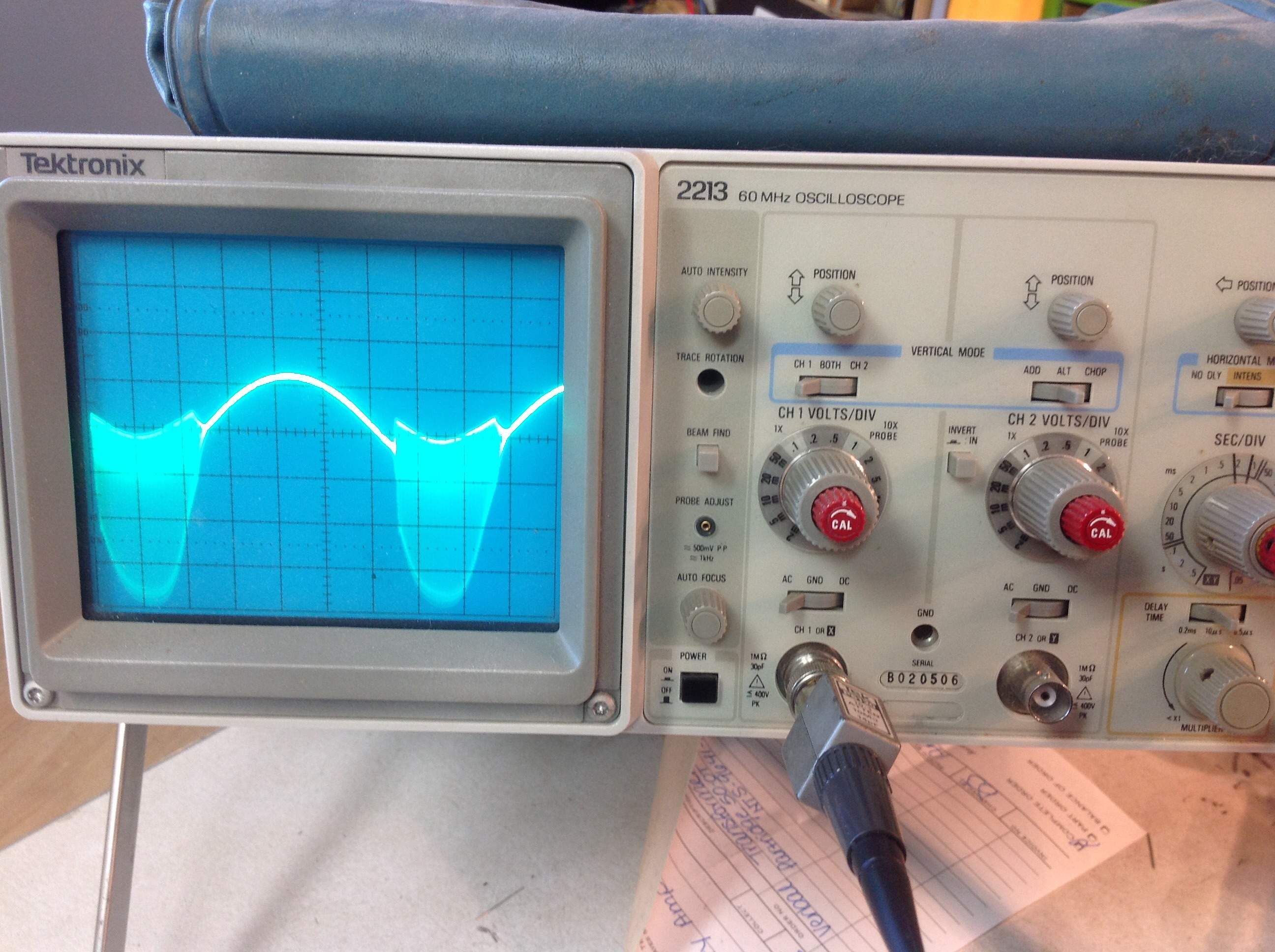
Out of interest, I would put the output through a spectrum analyzer and identify the offending frequencies are.
I would first try different tubes, NOS 6SL7 if you have them. I've found some 6SL7's that will oscillate. If you can, try a makeshift shield over the tube. The proximity to a transformer might be inducing an oscillation.
Although you are using a 10K feedback resistor off a 16 ohm tap, the output transformer and speaker come into play. Try clipping on a small valued capacitor parallel to the feedback resistor R36. Try around 1000pF (0.001uF) and see if it changes anything. If it does try different capacitor values and see how they affect the circuit.
They changed the PI plate voltages in the various B-15N revisions over the years. In the B-15NA, pin-2 was 310V, pin-5 was 309V, in the NC it was 235V and 225V, in the first Heritage it was 200V and 192V. The other voltages in the amp remained more or less constant.
Check under your board with a mirror. Look for a small solder bridge or a wire out of place. As was mentioned, capacitive coupling might be an issue. The board might be an issue but this is probably a long shot. The components are well spaced in your image. Pay close attention to the board mounting post (is it metal?) relative to the turret next to it.
See if it oscillates with a dummy load in place of the speaker. I like to isolate the speaker jack from the chassis (Switchcraft S1028 and S1029 washers). Try grounding the speaker return where the PI circuit is grounded. Ampeg's traditional ground bus works very well. It runs from the isolated power supply caps to the input jacks. The ground to the chassis is at the input jacks. This avoids ground currents in the chassis that can interact and induce noise in wires above them. Multiple ground points are fine if done properly.