- May 20, 2000
- 3,200
- 1,917
- Disclosures
- Endorsing Artist: Aguilar Amplification, Spector, Dingwall, Tech 21 NYC, Darkglass
Somebody else can spend some cash, Im passing the ball.
Pass received...

TalkBass has been independent since 1998. Add your voice.
Create a free account to reply to discussions, view embedded media, and browse with fewer display ads.
Join free Log in
Want zero display ads or expanded classifieds tools? Compare plans.
Somebody else can spend some cash, Im passing the ball.


Alex,
I just saw the retro 2x10 cab is being offered in 4ohm, and that the (same?) speakers can be rewired to be either 12ohm or 4ohm. I guess that means that my previous post is completely wrong and that my idea of speaker resistance is faulty. Would you mind explaining how impedance works with these drivers/cabs?
How can 2 12ohm drivers make a 4 ohm load? Here's the bit I read on your website:
"The 4 ohm version exists for two reasons - getting maximum power out of low power amps if you intend to only use one cab or for using with valve amps whose highest impedance tap is 4 ohms. Two cabs can be used with amps which run down to 2 ohms. If you wish to add more Two10s and need your 4 ohm cab to run at 12 ohms then it be converted from one impedance to the other by replacing the wiring loom, crossover and rear panel - a simple job as it's a complete modular assembly with no soldering required."

Sorry, that got a bit long!




 ).
).
I'd guess it's either aperiodic or tuned very low like Duke talks about to simulate a sealed roll off? Or a British variant of MVW (<--joke!
You're halfway there with one of them!
Right, so the impedance thing. I know most bass players think a 4 ohm cab is 4 ohms all the time and an 8 ohm cab is 8 ohms all the time but that that couldn't be further from the truth!
When designing a driver one of the first things you decide on is the target impedance. You then have this complicated juggling act of wire material and gauge, length of voice coil, number of layers wound, and then that gives you the total length of wire on the voice coil and thus the DC resistance of the coil. Changing any of these physical properties also changes the inductance Le, the magnetic force BL, the moving mass Mms, the maximum clean excursion Xmax, and the maximum excursion before permanent damage Xlim. Changing those parameters also changes the resonant frequency Fs, the total Q Qts, the compliance equivalent volume Vas, the EBP, the Vd, the calculated sensitivity and so on. It also changes the tone through the midrange and treble. So as you can imagine it's not a straight forward affair in the slightest!
That voice coil then needs to be matched up with a suitable cone, dust cap, surround and spider(s) to create your driver model. Once you have your driver simulation you can then model the impedance and the low frequency performance. If both are in the right ball park then you make a physical sample and test it to see how it sounds/performs, particularly through the mids and treble (because you can't model that, it's too complicated - although you can certainly predict approximately what's going to happen if you've got a decent feel for how loudspeakers work and understand the parts you're using).
Now the thing about the impedance is it's a very long way from a simple flat line - in free air you get a peak at resonance whose height and width depends on the resonant characteristics of the driver and then it starts rising at higher frequencies due to the inductance. Once you put the driver in a cab that changes the low frequency impedance because you're changing the resonant system.
The DCR of your voice coil is lower than the target impedance because the driver exhibits both inductive and capacitive reactance both of which add to the DC resistance to create the actual impedance. When you first set out with your coil design you have to figure in how those two aspects of reactance will add to the resistance to create the impedance. You don't want to start out with too high a resistance and end up with your driver having excessively high impedance compared to the nominal target as that will cost you in voltage sensitivity but you don't want to have too low a resistance or you'll cause amp shutdowns (destructive failures are rare nowadays). Also you can't vary the DCR continuously - wire comes in specific gauges, winding layers are one, two, three or more and you can't stop halfway around a turn! And changing the gauge or layers drastically changes the BL whilst changing the length drastically changes Xmax/Xlim.
There are yet more issues - impedance is a vector quantity with magnitude and phase. Inductive reactance pulls the impedance into positive phase angles whilst capacitive reactance pushes it negative. Negative angles are much harder for amplifiers to drive than positive.
The DC resistive component of impedance varies hugely with temperature - impedance is quoted at room temperature but at full power your voice coils will be at around 200 deg C and your impedance will have doubled.
We've generally erred on the side of caution (the higher side) with the actual vs nominal impedance of our new driver designs - why?
1. Gen 3 cabs are loud already so we don't need to squeeze extra watts out of your amp
2. Some Gen 3 cabs have complex crossovers which make them more challenging to drive due to shunt coils dropping the impedance and series caps pulling the phase negative.
3. The Gen 3 cabs have huge thermal power handling so they don't get as hot and increase in impedance as much when you're playing loud.
4. Our Gen 3 cabs have big well-tuned ports which act as a capacitive component pulling the phase negative again.
The end result of this is that the Gen 3 12XN cabs are all nice loads to drive.
The Retro 10CR driver was designed as a 6 ohm driver so our new 6x10" would be 4 ohms. The final driver design we settled on is a particularly easy load to drive with the minimum impedance in free air not dropping as low as the norm. The hybrid resonator enclosure further raises the average impedance in the sub 150Hz region. There is that added capacitance higher up though and it's a series crossover so it drops the impedance more than a parallel crossover would. Also with six moderately large voice coils there's a lot of thermal power handling and thus minimal impedance rise due to heating. With the performance and tone we were getting there was no need to try and squeeze the impedance lower for more voltage sensitivity so the Retro Six10 was left as a very easy to drive 4 ohm nominal load.
The Retro Two10 is simply one third of a Six10. Hence the 12 ohm nominal impedance with one third of the drivers, crossover and wiring loom.
I realise that designing around six 10" drivers is unconventional but it just makes more sense to us for use with old school / valve amps than the "rarely loud/fat enough" sealed 4x10" or the "usually louder/fatter than you need" sealed 8x10". Yes our Retro10 cabs aren't technically sealed but they're more like sealed cabs in terms of sensitivity than ported cabs. It may be a more difficult marketing challenge than selling an 8 ohm 2x10" but hopefully our target market will understand!
So, finally back to the 4 ohm 2x10". After we put the Retro Two10 on our site there was quite a bit of impedance related discussion online and I went back to look at our various documents and measurements. And that got me thinking... Almost every valve or solidstate amp on the market will drive a 12 ohm nominal load very happily - the only exception I can think of are valve SVTs which have 2 and 4 ohm taps but no 8 ohm tap. If we parallel rather than series wire a version of the Two10 then SVTs can drive a single cab without worry.
Therefore we could offer a lower impedance alternative for SVT users (a great recording or small gig cab!) Due to the parallel wiring we'd need a different crossover and this crossover would have no capacitive component (reducing the negative phase angle) and would also raise the magnitude of the impedance at mid/high frequencies.
This means that the lower impedance version would be a particularly easy load for its nominal impedance - so I did some modelling of a variety of 4 ohm bass cabs on the market, particularly focusing on the impedance minima and the phase angle at those points. We compared our model of the Two10 low impedance version to those cabs and it came out very well, especially considering that a simplistic analysis would declare it to be slightly lower nominal impedance.
We need to test what happens in practice with a variety of solidstate amps whose minimum load is 4 ohms but based on all our measurements, simulations and the comparisons with other bass cabs I think it should be fine and thus can be deemed a 4 ohm nominal design.
Sorry, that got a bit long!

The 'hybrid resonator' is neither sealed nor a conventional ported system. It came about from us looking into ways of improving the output of a sealed cab without really changing the tone or feel. Not sure I want to say more than that at the moment - I'll see if anyone can work out what we're doing!
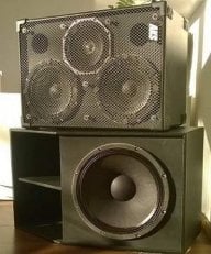
The 'hybrid resonator' is neither sealed nor a conventional ported system. It came about from us looking into ways of improving the output of a sealed cab without really changing the tone or feel. Not sure I want to say more than that at the moment - I'll see if anyone can work out what we're doing!