• TalkBass has been independent since 1998. Add your voice.
    Create a free account to reply to discussions, view embedded media, and browse with fewer display ads.
    Join freeLog in
    Want zero display ads or expanded classifieds tools? Compare plans.

Biasing mti svt, am I doing this wrong?

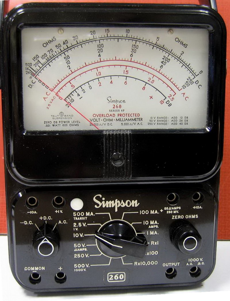
Back when I was an AF technician, I think the Simpspon 260 was the standard issue analog multimeter. The thing is, the lowest range on a 260 is 1V. With this level of sensitivity, I don't think I would be quibbling over 2.5mV :cool:.

simpson_260-6p-1-001.jpg

I have one. Interesting to note that they are still in production.


Invalid Link Removed
 
20190912_210629.jpg
and from here it looks good. However when I run it up to 25 volts, it is no longer happy here. Using the scope the pot is set to almost straight up and down as that completely eliminated the distortion at all volumes. At that voltage level, there is ~10 mv difference between the two sides. However, it's that clean on the scope at that level and sounds great.
 
@poorbassist15 it's unclear what conclusion you are drawing.

The Balance adjustment should not effect the DC reading for K1 to ground, K2 to ground, or K1 to K2, when no signal is applied. The position of the Balance adjustment should only be relevant when an AC signal is applied.
 
View attachment 3536992and from here it looks good. However when I run it up to 25 volts, it is no longer happy here. Using the scope the pot is set to almost straight up and down as that completely eliminated the distortion at all volumes. At that voltage level, there is ~10 mv difference between the two sides. However, it's that clean on the scope at that level and sounds great.
This is not correct, your symmetry is way off. The shape of the waveform at the top and bottom are not right and if you put a THD analyzer on it you would probably see between 8% and 12%.

What does the scope look like when you set the balance to read 0mV between K1 & K2 at 25 volts into a 4 ohm load on the 4 ohm tap like the manual says?
 
There are 2 things going on, there is symmetry and there is crossover distortion. Your symmetry is off on the bottom of the waveform. It's possible that there is an additional problem with your amp.

What frequency did you use when testing for crossover distortion? If you are really using 40Hz, what you may be seeing as far as the symmetry problem is really low frequency non-linearity which could be normal for that amp (I don't recall)

Do the same test at 400Hz, it will make the crossover notch MUCH easier to see and adjust for, adjust until it just disappears and no more. I bet things will agree more.
 
Yes, do the same thing at 400Hz, 25V and with the expanded scope scale you will be able to see things much more clearly. It may be even more clear at 5 volts, allowing the crossover notch to represent a greater portion of the vertical scale.

When designing solid state amps, I use 10kHz and about 5 volts which makes every biasing and symmetry flaw jump right off the screen. (except for clipping symmetry, different problem)

Something else to try, increase the bias voltage readings from 72mV to 100mV and see if the notch gets a lot better before setting the symmetry. The handoff between sides is not a linear transfer function, sometimes increasing (or decreasing) the bias slightly can make a big difference. Since the amp is baised pretty cold, adding a little more MIGHT make a big difference. If it doesn't, leave it at 72mV

Also, if the symmetry problem on the bottom goes away as the frequency rises, it's probably just an artifact of the transformer and the global feedback around it.
 
  • Like
Reactions: Wasnex
The purpose of the balance control is to adjust for minimum total harmonic distortion which can be heard as noise.

If you had a spectrum analyzer, the harmonics generated by using the test tone could be seen. This gives you an indication as to how well amp is calibrated. Of course if your test tone source has noise in it, this will be translated through the amp. When using a scope to look for a notch, the spectrum analyzer is a good companion instrument. The point of onset of the notch can be difficult to identify, it’s subjective. I find that using a spectrum analyzer in conjunction helps to that end. ....then there’s always the option of using a distortion analyzer.
 
Last edited:
  • Like
Reactions: Wasnex
It's distorting again. I got through the show (and it was a loud one). I think I have a cathode follower failing, at least it's easy to check, I have a tester at work.
Measure voltages and look at the waveforms to identify the problem first, that way you will know if the conditions are correct when you are done.

Changing the cathode follower is just a wild guess, troubleshooting will get you a lot closer. Did you verify that each output tube is sharing the proper amount of current? This is kind of important when troubleshooting this sort of symptom IME.
 
You're right, it is a wild guess, but it's a simple thing to check, and it wouldn't take much time. I will have to open it up this week and measure individual current. I've definitely isolated it to the power section. Plugging in directly to the power amp in left me the same result. I had hoped it wasn't a major issue, but it is, so I will continue to look for the problem.

Once again, thanks everyone for all the help.
 
Here is a video compilation showing my issue. I thought this would be better than trying to explain it

So it appears the side of the amp that is making the top of the wave form is nice and strong and the part of the amp that is making the bottom of the waveform is weak. At 2:29 the waveform looks relatively clean but Vmax is 60V and Vmin is -40V so there is some serious asymmetry. Later, when you adjust the balance to resolve the asymmetry you get some nasty distortion on the lower part of the waveform.

It should be fairly easy to localize the problem with an O'scope by probing the circuit, as long as your probe is configured to, and can handle the voltage. If you don't have an appropriate probe you need to be very mindful about the voltages you are probing.

I may be as simple as a bad driver tube. You could bias the amp cold, swap the drivers, reset the bias, and see if the problem follows the tubes. If problem does not follow the tube, you need to pull the chassis and start trouble shooting.

I think checking the current balance in all the output tubes would be a good place to start. It's possible one side of the amp only has 2 of 3 output tubes operating. If the current in the output tubes is reasonably balanced, I would trace the signal through the amp from the output of the PI to the output of the drivers.

To determine the state of the output tubes, you can measure the voltage drop across the screen resistors and also the plate resistors. Of course the standard warning applies here...be very careful as you will be probing lethal voltages. If you are not competent and comfortable working with high voltage, take the amp to a technician. One of the first things you should do is take off rings and necklaces, and generally you should probe with only one hand. The idea is if you do get shocked, you don't want the electricity going from one hand to the other through your chest cavity, as that can stop your heart.
 
Yes, with no signal, and the bias set for 72mA per side, measure the voltage drop (DC) across each of the 10 ohm resistors, they should read about 225mV each. If it's different by more than +/-20% that signifies that there is something wrong within the output stage and you need to slow down and take it step by step, systematically.

1. with no power applied and no residual voltage on the rails, verify that each 10 ohm resistor actually measures 10 ohms within the tolerance stated on the part.

2. Verify that each screen resistor measures the value that it's supposed to be within the tolerance on the part.

3, Verify that the grid resistors measure the correct value too, though a failure here is unusual.

Now, for the AC current balance (which measures a different set of related parameters):

1. Yes, with 25VRMS into 4 ohms, and the bias set for 72mA per side, measure the voltage drop (AC) across each of the 10 ohm resistors, the values may not be accurate depending on how the meter measures 1/2-wave signal, but the values should be within at least +/-20% and probably within +/-10%. If not, if the values are lower all on the same side than it's likely something in the PI or cathode follower driver tube/circuit.

2. If there is one reading that is very low, it's likely that the tube is very weak and could be upsetting the plate impedance between sides which can skew the symmetry under load yet look ok with static DC bias.

Be very careful, did I mention this at least several times before?