• TalkBass has been independent since 1998. Add your voice.
    Create a free account to reply to discussions, view embedded media, and browse with fewer display ads.
    Join freeLog in
    Want zero display ads or expanded classifieds tools? Compare plans.

Chasis ground question

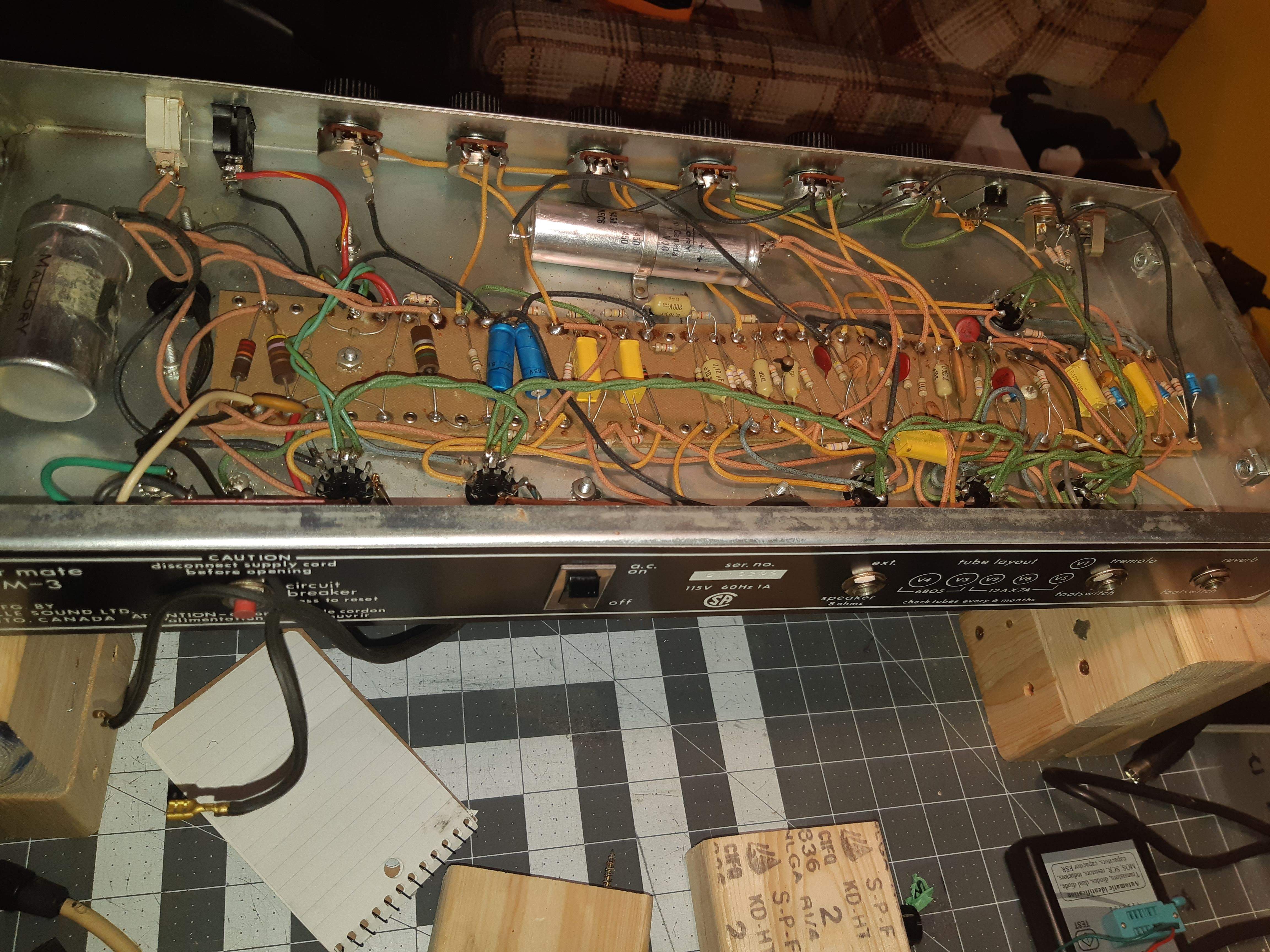
Hey guys I'm changing out some old failing filter caps on this old Traynor amp and just had a quick question. The amp grounding is wired different then most of the Traynors I have seen. I'll attach a pic... the ground wires are connected from a node on the far side of the amp and go all the way around the turret board to the cathodes of the two EL84's. At no point is there any soldered connection to the chasis, it looks like the only connection is the pots. It looks like this was done stock as I see no repairs other than the 3 prong power cable that was installed. Is it ok to leave it this way or should I make an actual soldered or bolted connection?
20200317_085131.jpg
 
It appears to me to be grounded to the chassis where the AC comes in and then bonded by the pots being seated on the chassis itself..although this is a bit out of my wheelhouse, so if any experts are here they probably have better info..

Yeah the AC earth ground is there but the pots seem to be the only ground on the actual circuit. Just never worked on a amp grounded this way before.
 
Are you getting a hum that is caused by bad grounding ?

What do you think will improved by altering the grounding?

It might be helpful to read this:
Grounding and Shielding Audio Devices
and pay attention to the distinction between chassis ground and signal ground. And understand what a star point is. And why trouble may occur when we connect unbalanced equipment to balanced equipment using off the shelve connectors.

These Rane bulletins are technical (boring). But extremely informative for all of us geeky DIY-ers.
 
Are you getting a hum that is caused by bad grounding ?

What do you think will improved by altering the grounding?

It might be helpful to read this:
Grounding and Shielding Audio Devices
and pay attention to the distinction between chassis ground and signal ground. And understand what a star point is. And why trouble may occur when we connect unbalanced equipment to balanced equipment using off the shelve connectors.

These Rane bulletins are technical (boring). But extremely informative for all of us geeky DIY-ers.

It sounds gawd awful right now because of the filter caps so I don't know yet haha. A few of the resistors are way out of spec as well so I just figured if anything needed to be changed while I'm in there doing all that work it would be a good time. Guess I'll just wait until after I'm done and aee how it sounds. It looks like it was done this way out of the factory so I'm sure it will be fine. I just thought someone might see something I'm missing. I'm still rather new to this and love learning from people more experienced than myself.
 
How about starting slowly and identifying the actual problems first an correct step by step BEFORE changing anything?

I've ran through the whole amp checking all the components. The caps tested horribly on the ESR meter. I know everything that currently needs to be replaced I just figured I'd try and get a 2nd opinion on the grounding while I wait.
 
I suggest starting with the power supply and get that working properly (though when looking at ESR values, be sure that you know what they are supposed to be based on the original part's factory specifications), then move onto the preamp, and then the power amp. Don't change everything at once, because IF you make a mistake and there is an issue, you won't know where to look first.
 
This sort of ground bus is not uncommon. Ground signals are often set up to flow from the high current to low current input end where they are grounded. This is exactly what Ampeg did on all of their vintage tube amps including the SVT, V4B, V22, B-15, B25B, etc.

The key is to ground only one end of the bus, either at the input OR at the first power supply node, not at both ends of the bus. Otherwise the is a ground loop and hum. A cap can would require insulation from the chassis if it is not the main ground point. This is a mistake people make when recaping an amp.

If the cap can is the main ground, connect downstream grounds to the bus. Do not use the pot cases as a ground point.

If the pot cases are the main ground, make sure that there is no oxidation behind the pots against the chassis. This provides a bad ground. Grounding at the pots is not the beast idea as you can’t easily inspect behind the pots without removing the nuts and pulling them back, this can break wires. For this reason, either an input jack is grounded or there is a chassis lug near the input jacks (better).
 
Last edited:
  • Like
Reactions: thetragichero
Hey guys I'm changing out some old failing filter caps on this old Traynor amp and just had a quick question. The amp grounding is wired different then most of the Traynors I have seen. I'll attach a pic... the ground wires are connected from a node on the far side of the amp and go all the way around the turret board to the cathodes of the two EL84's. At no point is there any soldered connection to the chasis, it looks like the only connection is the pots. It looks like this was done stock as I see no repairs other than the 3 prong power cable that was installed. Is it ok to leave it this way or should I make an actual soldered or bolted connection?

View attachment 3747333
How do you know the filter caps are failing?
 
  • Like
Reactions: agedhorse
It's also mechanically grounded to the chassis at the input jacks just like the pots. The Earth ground at the plug appears to be decently bolted to the chassis from the pic but hard to tell from that pic.

Theres a good FB group for Tube amp repair, 1065280143547025, a lot of knowledgable people.
 
Classic Traynor amps do, indeed, have different ground wiring, and if memory serves, also have different power tube grid wiring or biasing. They can be tricky, and just because a person can solder and unsolder all the parts of a blackface Fender or JTM 45 Marshall with their eyes shut (I don't recommend that), does not mean they can do the same for a Traynor. Google "Traynor Amplifier Forum" and you will see at least a half-dozen forums or subforums or specialty blogs that can focus on these great amps for help.
 
Classic Traynor amps do, indeed, have different ground wiring, and if memory serves, also have different power tube grid wiring or biasing. They can be tricky, and just because a person can solder and unsolder all the parts of a blackface Fender or JTM 45 Marshall with their eyes shut (I don't recommend that), does not mean they can do the same for a Traynor. Google "Traynor Amplifier Forum" and you will see at least a half-dozen forums or subforums or specialty blogs that can focus on these great amps for help.
I don't have a lot of respect for engineering when they try and re-invent the wheel, just for the sake of departing from the tried and true way of doing things.

All sorts of problems can crop up when multiple chassis grounds are used, due to circulating ground currents within the chassis.
 
I don't have a lot of respect for engineering when they try and re-invent the wheel, just for the sake of departing from the tried and true way of doing things.

All sorts of problems can crop up when multiple chassis grounds are used, due to circulating ground currents within the chassis.
Boy howdy is this true!

There's a grounding method called structured grounding systems where currents, voltage drops and reactive issues are used to insure that the grounds are functioning as expected. It's actually supposed to be equi-potential points, but in practice this isn't always true. I spend probably 25% of my design and layout time with new designs on the grounding system, to be sure that what I expect is what I actually get.
 
I don't have a lot of respect for engineering when they try and re-invent the wheel, just for the sake of departing from the tried and true way of doing things.

All sorts of problems can crop up when multiple chassis grounds are used, due to circulating ground currents within the chassis.
Um, it wasn't "just for the sake of departing from the tried and true way of doing things." It had to do with changing just enough so Jim Marshall wouldn't sue Yorkville/Traynor for copying his circuits, just like Jim Marshall changed the original JTM45 circuits just enough so Leo Fender wouldn't sue him (including using a 12AX7 instead of a 12AT7 for the phase inverter to change the gain characteristics, and using Mullard EL34's, KT66's and KT88's for power tubes instead of RCA 6V6's and 6L6GC's, which required different biasing and plate voltage transformers).
 
  • Like
Reactions: BassmanPaul
Um, it wasn't "just for the sake of departing from the tried and true way of doing things." It had to do with changing just enough so Jim Marshall wouldn't sue Yorkville/Traynor for copying his circuits, just like Jim Marshall changed the original JTM45 circuits just enough so Leo Fender wouldn't sue him (including using a 12AX7 instead of a 12AT7 for the phase inverter to change the gain characteristics, and using Mullard EL34's, KT66's and KT88's for power tubes instead of RCA 6V6's and 6L6GC's, which required different biasing and plate voltage transformers).
Many of those circuits were in the Radiotron Designers Handbook, developed in the 1930s and 40s and were nothing patentable or new under the sun. I think many of these wacky departures were due to trying to correct problems created because the designer didn't fully understand what they were doing.

It was natural that Marshall used and developed his products around European tubes, as they were more readily obtainable and cheaper in his locale. I don't think his selection of tubes had much to do with copyright infringement.

After working on many Traynor "designs" over the years, I find it humorous when people regard him as an under-appreciated genius.
 
Many of those circuits were in the Radiotron Designers Handbook, developed in the 1930s and 40s and were nothing patentable or new under the sun. I think many of these wacky departures were due to trying to correct problems created because the designer didn't fully understand what they were doing.

It was natural that Marshall used and developed his products around European tubes, as they were more readily obtainable and cheaper in his locale. I don't think his selection of tubes had much to do with copyright infringement.

After working on many Traynor "designs" over the years, I find it humorous when people regard him as an under-appreciated genius.
Yes, and Leo Fender kept that book and the RCA tube book on his workbench. But just because the basic circuits were in the book doesn't mean that each person contributed their own spin on them. Also, it wasn't just availability, because Jim Marshall also had access to American tubes, including 6L6's, which were what he first used.
 
  • Like
Reactions: byacey
Back in the day, circuits such as in the RCA books and application notes were free to use. Mullard published circuits with layouts, even showing builds in a chassis. This was done because they wanted to sell their tubes. Designers would cut and paste, talking an RCA power amp and combining it with another preamp, or tweaking the circuits.

Musical instrument amp design at the time wasn’t rocket science. Things were changed. Different tubes were used and designs were tweaked, for example, to differentiate one companies products from another. Both for marketing and for legal reasons. They couldn’t deliver an amp that was the same design and layout as a Fender. They wanted a different speakers and designs than what Fender used to distinguish themselves. For the same market, they all had to compete with Fender in terms of features, quality, and price. That was the hard part.
 
Boy howdy is this true!

There's a grounding method called structured grounding systems where currents, voltage drops and reactive issues are used to insure that the grounds are functioning as expected. It's actually supposed to be equi-potential points, but in practice this isn't always true. I spend probably 25% of my design and layout time with new designs on the grounding system, to be sure that what I expect is what I actually get.

Any analog audio system is best viewed as a ground system with other things piled on top of that. I've worked on enough amplifiers and the like to realize that it doesn't take much to mess up an otherwise clean design. A lot of old Fender amps can be made much quieter by re-doing the ground connections, but...don't try that unless you really know what you're doing.
 
Yes, and Leo Fender kept that book and the RCA tube book on his workbench. But just because the basic circuits were in the book doesn't mean that each person contributed their own spin on them. Also, it wasn't just availability, because Jim Marshall also had access to American tubes, including 6L6's, which were what he first used.
All the amp builders of the time didn't really drift very far from a standard push pull output, in itself standard enough that any good tech could service them without a schematic. Small changes in parts values were made to optimize (hopefully) for the power supply voltages, the chosen output transformer and the intended purpose, but overall there was nothing innovative, except perhaps when ultralinear came along.

Philips KT series output tubes were a superior tube in many respects, being able to withstand higher plate voltages and drive lower impedance loads in some cases, allowing for higher output power. This, and the fact they were manufactured in Marshall's backyard, and they were likely more cost effective to purchase locally, would have been good reason for Marshall to select them for his product offerings.
 
  • Like
Reactions: dabis and agedhorse

Latest posts