
• TalkBass has been independent since 1998. Add your voice.
    Create a free account to reply to discussions, view embedded media, and browse with fewer display ads.
    Join freeLog in
    Want zero display ads or expanded classifieds tools? Compare plans.

Custom stereo loop switcher/reverser

I am building a large effects/looping setup and am looking for a custom pedal to run my stereo DL4 and EHX 2880 around and/or through each other. I want to be able to choose which comes first so I can use the delay before or after the looper. Popping during switching will be a major concern because of the delay and loop recording. (duh)

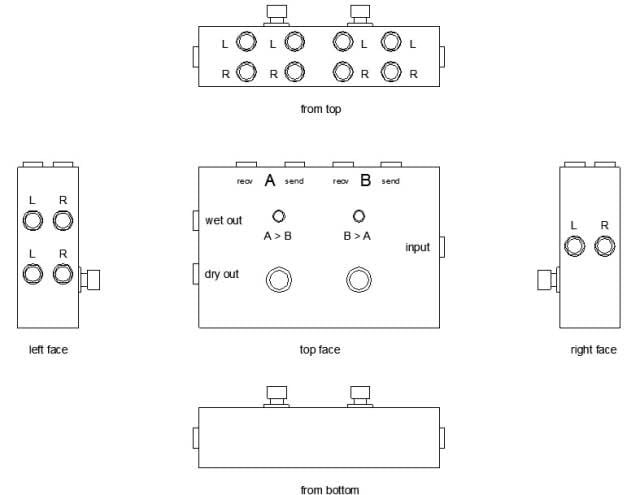
Here's a quick mock-up of what I think I want:
24pdqgn.jpg


Any reasons this wouldn't work? Any thoughts on who could build me one?

I have sent emails out to Loooper (though I realized afterward that he is out of commission for the time being :(), Toadworks (to see if they would build me a custom Roundabout Turbo), Red Onion, PepTone, and Barge.
 
I got some responses back from Peptone and Barge.

Apparently clicking might be an issue with the required switches in this setup. Geoff from Barge had a lot of questions, and some ideas which is cool. This thing might just get built yet.

Are there any units out there that can accomplish this I haven't thought of?
 
Pedalboards.com makes the Flip Flopper:
http://www.pedalboards.com/new_page_2.htm

If popping is a potential problem issue though, then you'd want to go with a buffered loop system, and the Flip Flopper may be true bypass if it's like their other loopers.
 
I am building a large effects/looping setup and am looking for a custom pedal to run my stereo DL4 and EHX 2880 around and/or through each other. I want to be able to choose which comes first so I can use the delay before or after the looper. Popping during switching will be a major concern because of the delay and loop recording. (duh)

Here's a quick mock-up of what I think I want:

24pdqgn.jpg


Any reasons this wouldn't work? Any thoughts on who could build me one?

I have sent emails out to Loooper (though I realized afterward that he is out of commission for the time being :(), Toadworks (to see if they would build me a custom Roundabout Turbo), Red Onion, PepTone, and Barge.

I don't recall you contacting us... I would have suggested our Roundabout Turbo - I think it already does what you want.

Oops - never mind - you're after a stereo setup... just not possible w/ 3PDT switches. :(
 
Right, but each loop has a send & a return - that's 2 'poles'... so you would need at least a 4PDT switch to have a stereo (regardless of if you use it that way, it's the same circuit requirement) loop switcher.... 5PDT if you want an LED indicator..

So, you basically have three options:

1) buy something off the shelf that already does all this... they exist but are expensive

2) have someone design you a fet-based switching system similar to the off the shelf systems... also very expensive

3) find some low voltage mechanical relays, and use a stomp-switch to feed power to them.

#3 is going to be the easiest and cheapest solution. It's simple - just wire the input and outputs for both loops to 2 different mechanical relays (one for each loop). You can use something like this:
Invalid Link Removed

Invalid Link Removed

$3 each, It's basically a DPDT switch that is activated by applying a positive voltage - in this case 9V DC, so it can be powered with any standard pedal PS.

The power to each relay would all be controlled by one switch - even a SPST switch would work.

If you really want the switcher you describe, this is your best bet.
 
Easy for you to say! :smug:

How would I go about having something like this built?

Also, I have slightly revised my idea to this:

2mhe7hg.jpg


Does this change what I would need to do to make this thing happen?

Thanks so much for taking the time to weigh in! :)

Assuming the center switch is a 'Y' (both A & B in parallel), yes, it changes things. It will need some active component to buffer the signals in both splitting and summing nodes.... but then it's no longer true-bypass.

To have something like this built, you'll need to find someone who does custom work as a hobby, that's the only way it would be affordable.

If I have time this week I'll draw up a circuit diagram that should do the trick. But I don't want to build it.

Wait.... just looked closer... what's the WET and DRY outputs for? If you want both sets of outputs to be live, this can't possibly be true bypass, even with relays.... in which case it's easier to design, but harder to build....
 
But I don't want to build it.

LOL! Any hobbyists looking to stretch their muscles?? :hiding:

Wait.... just looked closer... what's the WET and DRY outputs for? If you want both sets of outputs to be live, this can't possibly be true bypass, even with relays.... in which case it's easier to design, but harder to build....

Ugh. I am being so confusing! :rollno: The center switch is the inverter - either A>B or B>A, either/both/neither going to the wet output when active as determined by the other switches.

Yes, I would like the "dry" output to be always active, always bypassing both loops. True bypass isn't as much of a concern to me as is tone and noise since I will be running delays and recording loopers in the loops.
 

Latest posts