• TalkBass has been independent since 1998. Add your voice.
    Create a free account to reply to discussions, view embedded media, and browse with fewer display ads.
    Join freeLog in
    Want zero display ads or expanded classifieds tools? Compare plans.

DIY HPF Stompbox?

I was very efficient and had filed it away.

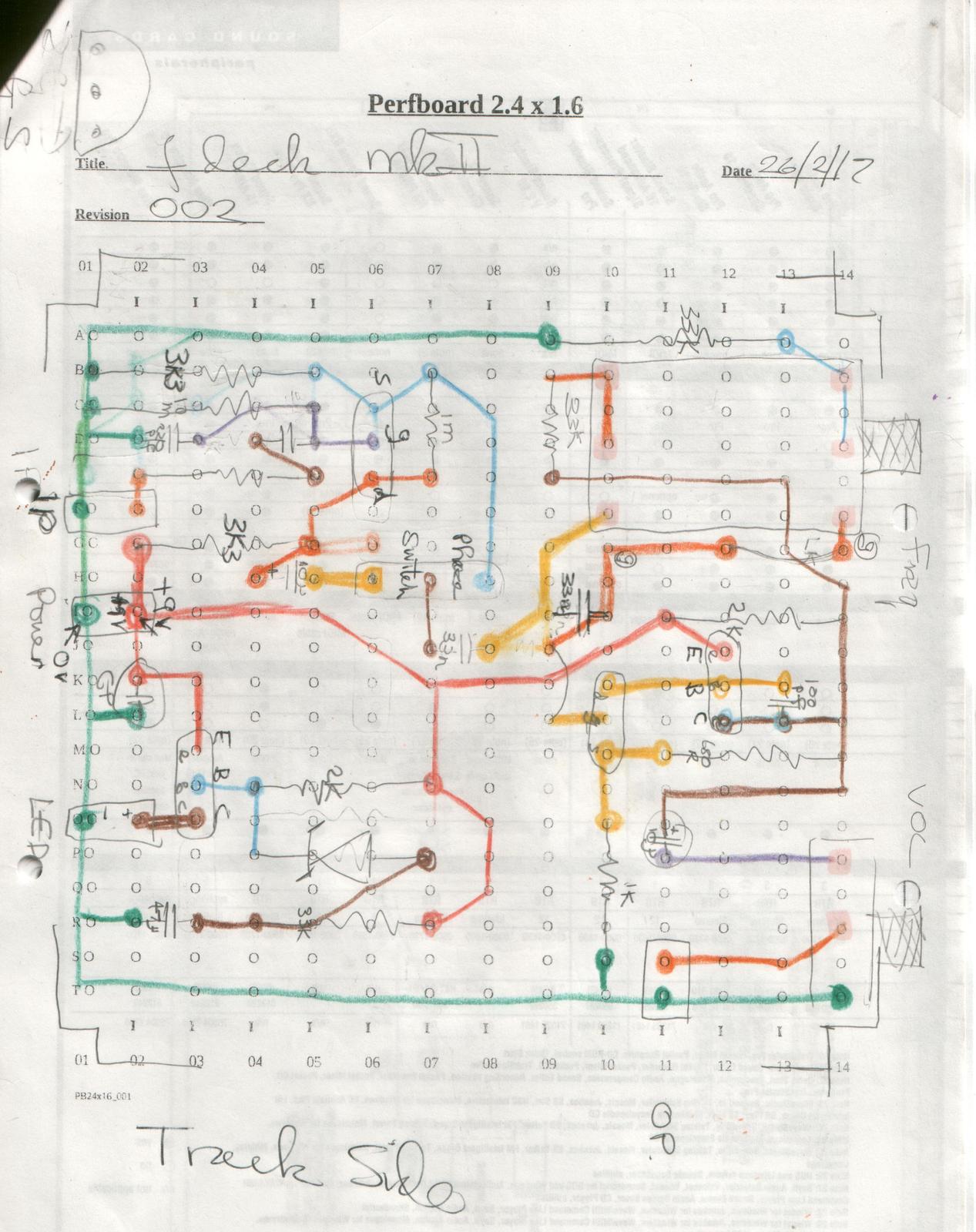
It is not my best layout (not kidding there), it was never meant for publishing so please excuse the mess. I think it is complete but give it a check over before you build it.

I bought smaller pots (the small green square variety) and rehashed the layout to suit and added an idiot diode across the supply rails.

The volume pot now has a switch so I routed the battery positive through that so I could leave it plugged in but turned off. I also added a tuner out directly across the volume pot so I could turn the volume down while tuning because this was originally destined to be fitted in an EUB (it got superseded before it was fitted so now is in pedal format).

All ins and outs are on the 0.1" pitch pins soldered to the board and female connectors on the wires (as used on PC motherboards etc) because I hate wires soldered directly to boards with no strain relief.
1guTCAt.jpg
 
Congrats Leonard! Looks good (holes/knobs are straight/even) and it works.

Thanks for inspiring me to fire up my own solder iron.


I was very efficient and had filed it away.

It is not my best layout (not kidding there), it was never meant for publishing so please excuse the mess. I think it is complete but give it a check over before you build it.

I bought smaller pots (the small green square variety) and rehashed the layout to suit and added an idiot diode across the supply rails.

The volume pot now has a switch so I routed the battery positive through that so I could leave it plugged in but turned off. I also added a tuner out directly across the volume pot so I could turn the volume down while tuning because this was originally destined to be fitted in an EUB (it got superseded before it was fitted so now is in pedal format).

All ins and outs are on the 0.1" pitch pins soldered to the board and female connectors on the wires (as used on PC motherboards etc) because I hate wires soldered directly to boards with no strain relief.

1guTCAt.jpg

VERY COOL!

Thanks for posting your perf-layout. I really like the pitch pin idea.
 
Sorry for necromancing, but I do have a question.

I just finished soldering everything in place and I really like the result. However I did not use a volume pot, because to me this shall be an always-on box and I dont't want to mistakenly turn it down.

But now I find that the hpf amplifies the signal. Will this be mitigated by a 10k resistor (like the pot) from output to ground? Or what's your advice on getting a 1:1 signal?


Best,
guitarrophobe
 
Will this be mitigated by a 10k resistor (like the pot) from output to ground? Or what's your advice on getting a 1:1 signal?

You could use a 10k preset resistor (that you adjust with a small screwdriver) so it is set and forget.

Or 2 resistors as a potential divider whose total value is somewhere between 10k and 20k (it is not critaical), adjust the values until you get unity gain.

--- from C13
/
\
/
\
------- output to jack socket
/
\
/
\
----- 0v

(Hope my high tech schematic mkaes sense!)

Quick update on the one I built.

A few weeks ago I became the proud owner of a DB (a CCB, BSO - Cheap Chinese Bass, Bass Shaped Object as they are generally known to the DB stalwarts) and my Fdeck II clone is now attached to the string anchor (is that the correct term ?).
 
Last edited:
Anchor works for me. Most call it a "tailpiece".


For the Volume pot conundrum... @guitarrophobe, I recommend either:

Socket the resistor that's replacing your volume pot, then you can try different values of resistors to get unity gain.

Another way to go would be using a trimpot inside the box, on its own or in series with a resistor — get close with the resistor and then the trimmer lets you dial in unity gain (or slightly above or below), close up the box and you're good to go.


Various types of trimmers
220px-12_board_mounted_potentiometers.jpg


Given that the pot being replaced is a 10K, I'd most likely go with simply a 10K trimmer, but if that didn't have enough "finess" or fine-tunability, then I'd try something like a 5k resistor in series with a 5k trimmer — I don't know for sure, haven't tried it.
 
Looking at JohnK's layout and the schematic, is there a reason that a BC547 is recommended as an alternative to the 2N4403, when the 4403 is a PNP type, and the 547 is an NPN?

There's probably a very good reason, and I've missed it to be honest.