
Enjoy the benefits of a premium membership!
Upgrade Account
-
TalkBass has been independent since 1998. Add your voice.
Create a free account to reply to discussions, view embedded media, and browse with fewer display ads.
Join free Log in
Want zero display ads or expanded classifieds tools? Compare plans.
You are using an out of date browser. It may not display this or other websites correctly.
You should upgrade or use an alternative browser.
You should upgrade or use an alternative browser.
More options
Who Replied?
I don't know if this helps you in any way but Warwick have started using lithium-ion batteries for the electronics in their custom shop preamps (Invalid Link Removed). Maybe this can serve as some inspiration to you

Does anyone have experience in embedding an effect in bass? I am about to put an octave effect into my stumpy and am wondering how best to get power to it. I think it will consume too much power to make batteries acceptable. I am not sure if using a stereo plug would lead to noise/hum having that run in the same cable as the outbound audio.
There's a 66 Jazz at Real Guitars in SF all hippied out with an MXR 90 embedded in it.
does it just use an onboard 9v or is there external power?There's a 66 Jazz at Real Guitars in SF all hippied out with an MXR 90 embedded in it.
does it just use an onboard 9v or is there external power?
I'll take a pic when I swing by.
Main guy at that shop knew the owners one of the shops I worked in in the late 80's/early 90's.
I randomly called them yesterday fishing around for a beater.
Was working on my Spector and realized how many spare pickups and preamps I have laying around.
Somehow they got in pre-CBS Jazz's and a bunch of 70's.
I'll take pics of those, why not.
I was like, I have a bunch of pickups and preamps, but I don't feel like immediately routing out anything worth about a used Honda Civic.
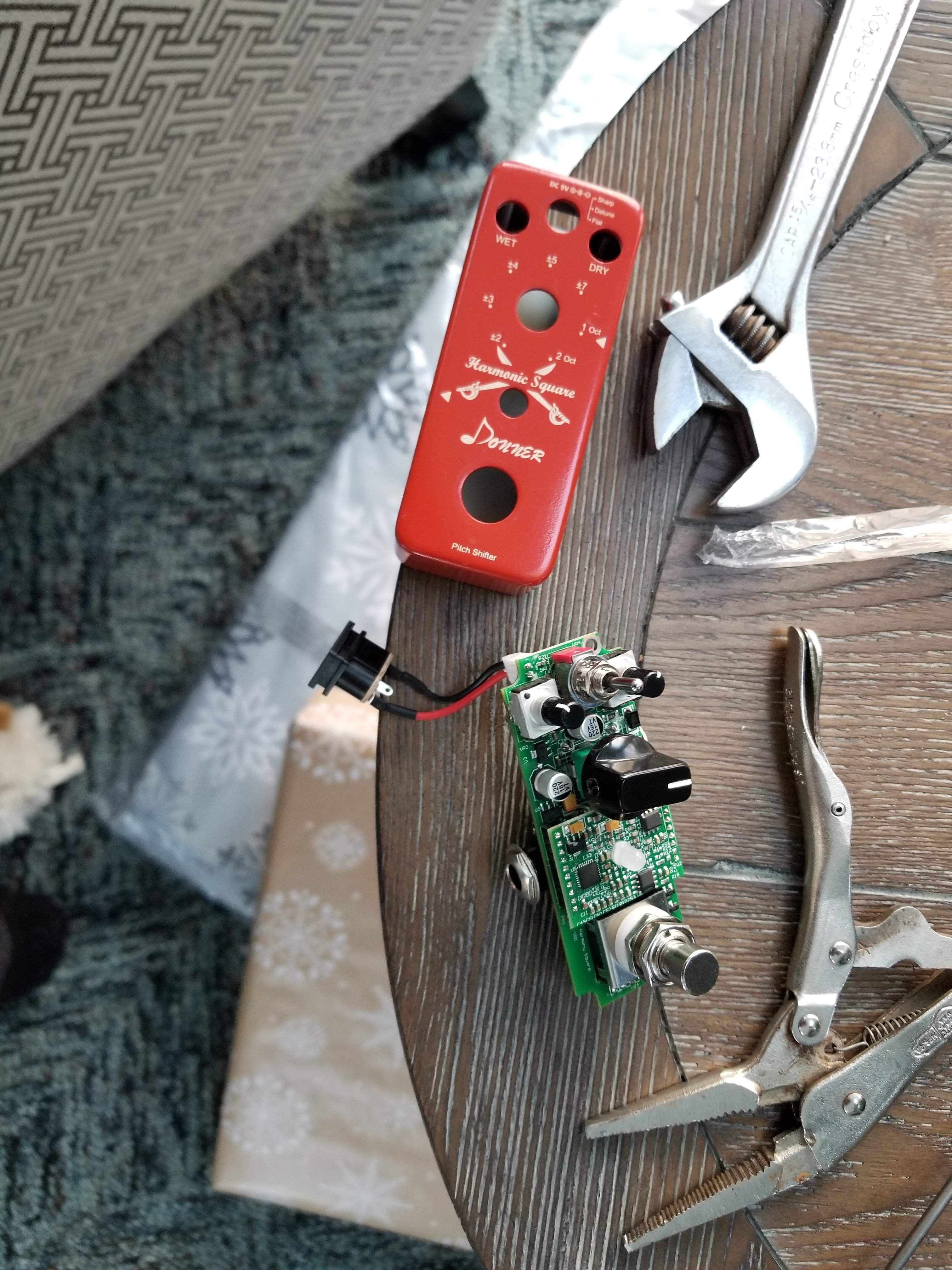
Santa brought me a POG, so let's tear into this Donner and see what we're up against.
First challenge is replacing the foot switch with a regular switch, that seems to be an easy one. Simple 3PDT switch, I found one on Amazon for $6, it's got some weird connections that I don't fully understand, but I can easily replicate the traces on the circuit board (even the ones that don't seem to be doing anything).
The second challenge will be removing the jacks. I may use a grinding wheel and just grind them away rather than trying to remove them. I can't see exactly how they are held in place. As long as there's room inside the cavity then it's not crucial I remove them completely, they certainly don't add much weight.
I'll use the faceplate as a template and just leave all the controls in the same spots, again pending room inside the cavity.
I'll be using an on board battery, I'm going to look into Lithium Ion rechargeables (thanks @arctur !), the control cavity cover is held on by magnets, so getting in there and swapping batteries is not hard at all.
First challenge is replacing the foot switch with a regular switch, that seems to be an easy one. Simple 3PDT switch, I found one on Amazon for $6, it's got some weird connections that I don't fully understand, but I can easily replicate the traces on the circuit board (even the ones that don't seem to be doing anything).
The second challenge will be removing the jacks. I may use a grinding wheel and just grind them away rather than trying to remove them. I can't see exactly how they are held in place. As long as there's room inside the cavity then it's not crucial I remove them completely, they certainly don't add much weight.
I'll use the faceplate as a template and just leave all the controls in the same spots, again pending room inside the cavity.
I'll be using an on board battery, I'm going to look into Lithium Ion rechargeables (thanks @arctur !), the control cavity cover is held on by magnets, so getting in there and swapping batteries is not hard at all.

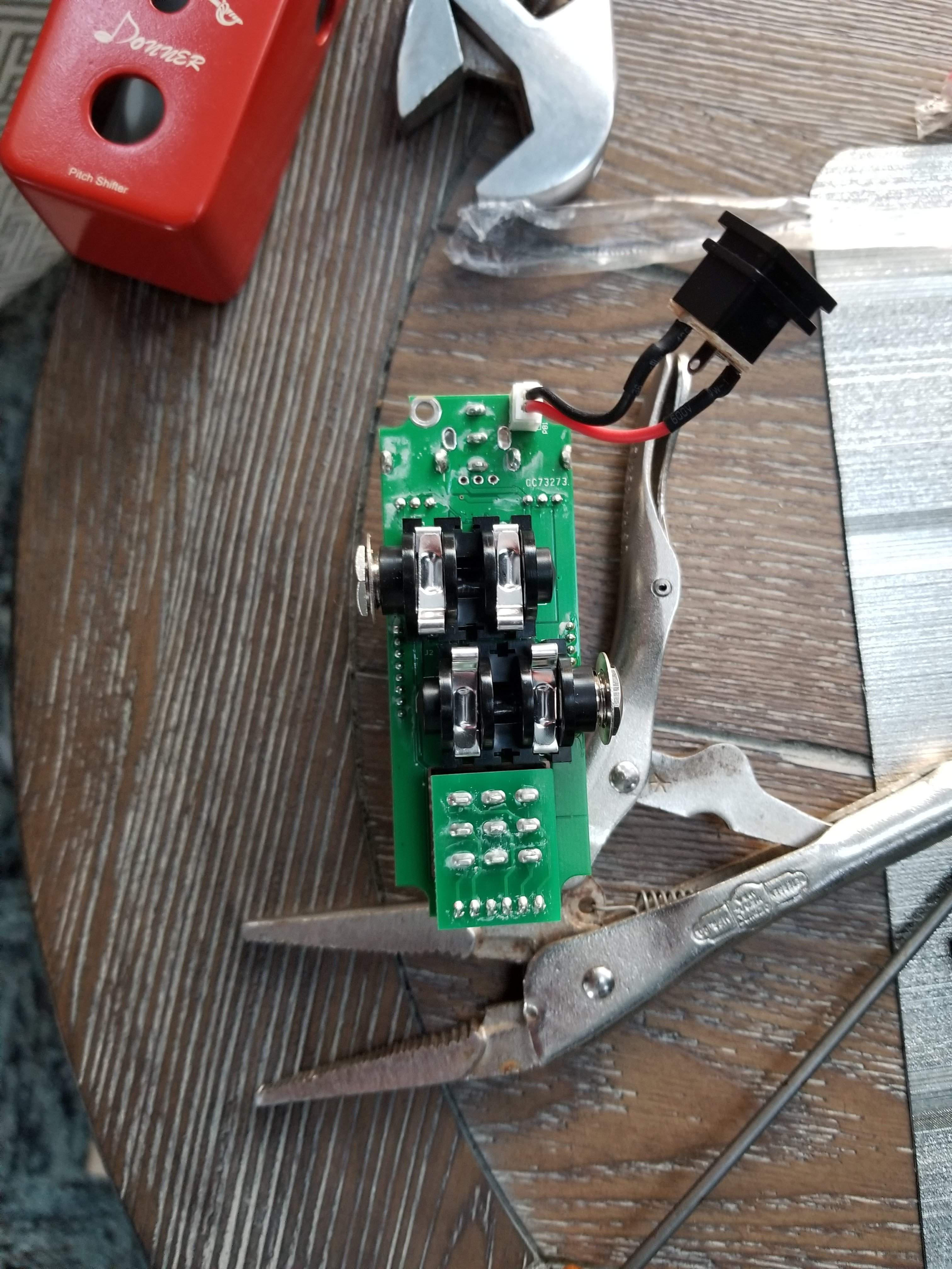
The jacks are connected by 4 solder joints each. They're underneath that daughter board.Santa brought me a POG, so let's tear into this Donner and see what we're up against.
First challenge is replacing the foot switch with a regular switch, that seems to be an easy one. Simple 3PDT switch, I found one on Amazon for $6, it's got some weird connections that I don't fully understand, but I can easily replicate the traces on the circuit board (even the ones that don't seem to be doing anything).
The second challenge will be removing the jacks. I may use a grinding wheel and just grind them away rather than trying to remove them. I can't see exactly how they are held in place. As long as there's room inside the cavity then it's not crucial I remove them completely, they certainly don't add much weight.
I'll use the faceplate as a template and just leave all the controls in the same spots, again pending room inside the cavity.
I'll be using an on board battery, I'm going to look into Lithium Ion rechargeables (thanks @arctur !), the control cavity cover is held on by magnets, so getting in there and swapping batteries is not hard at all.
View attachment 2854117 View attachment 2854118

Ok, I'll look closer, thanks for the intel.The jacks are connected by 4 solder joints each. They're underneath that daughter board.

Really, I have three here that I've tried to use in two different instruments and they are too hot, they distort no matter what I do. I have bought a few necks from them that have worked out amazingly well.

This exists. It comes like that from the factory.
Unfortunately the power situation on those is a mess.
I picked up a new one on sale this summer for less than then cost of the Kaoss Pad on its own and ended up ripping all the electronics out and using the bass and KP separately.
Half because of power issues, half from other issues with the internal electronics.
From the factory, the bass has a 9V battery inside powering the preamp (with no EQ or tone control), plus a distortion circuit, a headphone amp and a switchable stereo effects loop.
The Kaoss Pad is in the loop, running on 4.5V from its own internal set of 2 AA batteries. It has a pretty high milliamp draw because they die after about 3 hours.
On top of that, the Kaoss Pad takes a good 10-15 seconds to boot up when you turn it on, and defaults back to the low pass effect patch every time, so you really can't turn it on during or between songs in a set and have it ready when you need it.
All that said, a friend of mine designed an amp that sends 9V power to pedals via a proprietary cable that's 1/4" TRS on the amp end end and splits out to regular TS and Boss power plugs on the other.
It works perfectly fine with no hum issues. As long as you don't lose that cable.
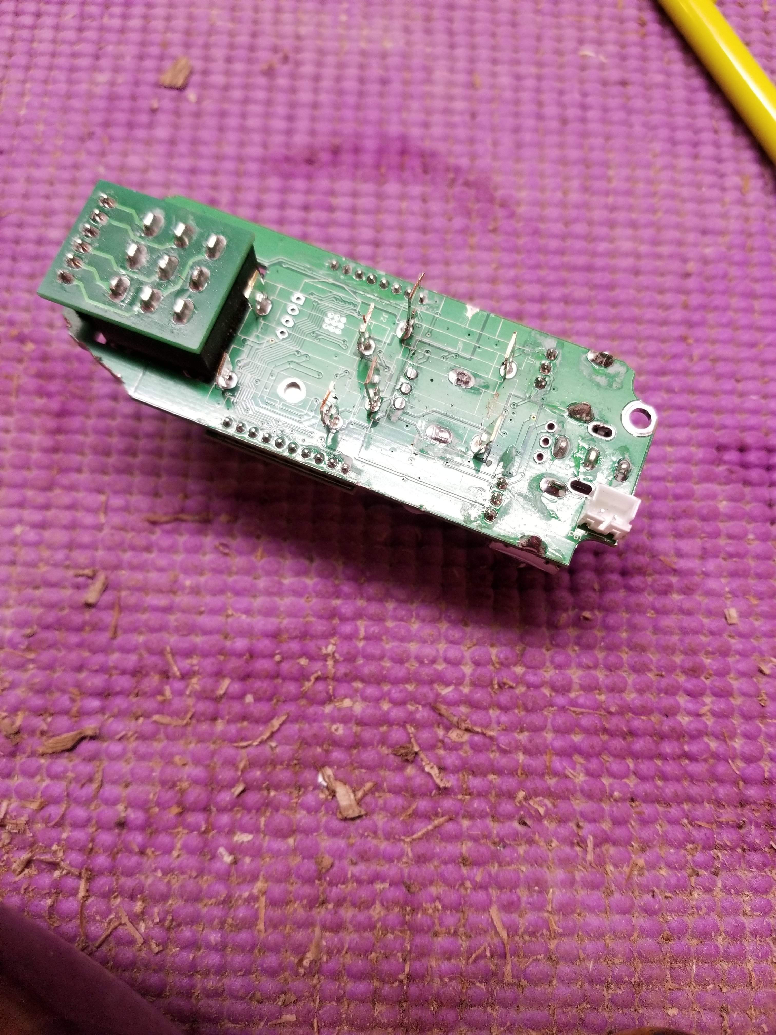
I guess I'm moving forward here. I got the jacks off the board. While they are indeed soldered to the board, it would be impossible to get to the solder joints without removing the daughter board, more pain that I was ready to endure. the contacts for the jack (which are what is soldered in) are actually the only thing holding the plastic blocks in place. So I carefully cut the angled part off the contacts and I could pry the plastic blocks up. I cut as much of the circuit board away as I could, the smaller that thing is the better.
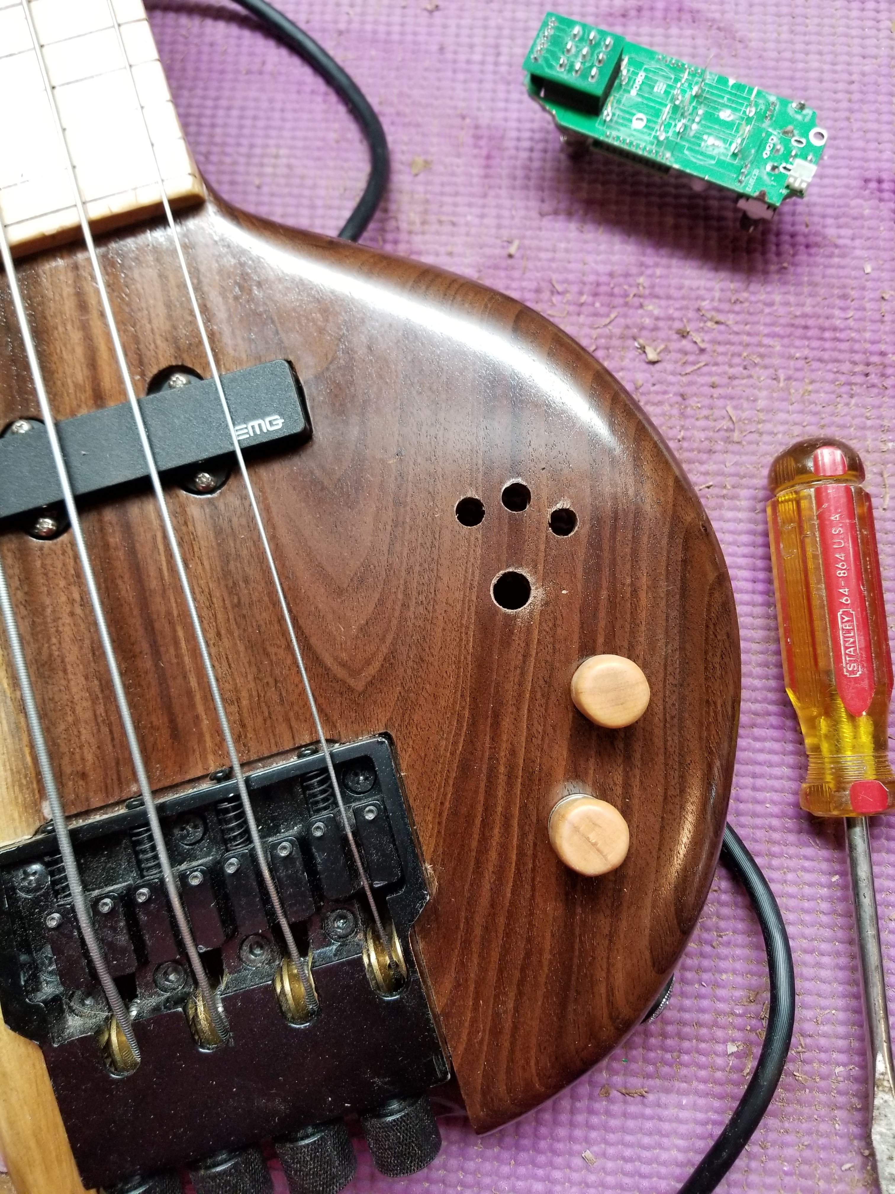
I located the switch that's on the pedal inside the cavity and drilled from the inside out. This is a dangerous thing to do because any chipout would be visible. I did the switch this way because it has a washer around it so as long as the chipout wasn't bad, it would be covered (it ended up not chipping out at all). Once I got that hole drilled I could locate the other holes and I drilled them from the front. If the drill wanders as it goes through the wood at least the front holes will be correct. I have a few more to drill, but I'll wait until the switch gets here on Friday to do that. There's no turning back now, I've not only butchered the pedal, but also drilled holes in my stumpy bass. I kind of wish I could choose where to put the controls, but these are surface mount controls and not easily removed. I'll try to balance things out with the on/off switch.
I located the switch that's on the pedal inside the cavity and drilled from the inside out. This is a dangerous thing to do because any chipout would be visible. I did the switch this way because it has a washer around it so as long as the chipout wasn't bad, it would be covered (it ended up not chipping out at all). Once I got that hole drilled I could locate the other holes and I drilled them from the front. If the drill wanders as it goes through the wood at least the front holes will be correct. I have a few more to drill, but I'll wait until the switch gets here on Friday to do that. There's no turning back now, I've not only butchered the pedal, but also drilled holes in my stumpy bass. I kind of wish I could choose where to put the controls, but these are surface mount controls and not easily removed. I'll try to balance things out with the on/off switch.
I got the replacement switch today, I was holding it sideways when I soldered connections on it the first time, ugh. I drained one 9v immediately. I had one more battery. I reconnected the switch the correct way (verified with an ohm meter - which I should have done first). It still drained the battery fast, the 9v battery was hot, so something is wrong. At this point the battery in my VOM died and I don't have any more here, so I'll have to wait for the rechargeables to charge up and see what's going on. I think there's something wrong with the way I connected the input/output, I'll have to look at it again tomorrow with a clear head.

One of the jacks, I think usually the input, probably had a switch to turn the battery on when a cord was plugged in. Could something have happened there when you removed the jacks from the circuit board?
Yes, that's what I'm thinking. Right before my vom died I was seeing shorts in unexpected places, I'll figure it out tomorrowOne of the jacks, I think usually the input, probably had a switch to turn the battery on when a cord was plugged in. Could something have happened there when you removed the jacks from the circuit board?
I’d like to be more help but I would have to have the board “in hand.” Still working on my long distance diagnostic techniques.
I appreciate any help! If I had a schematic this would be easy, the traces are so tiny on this double sided board, it's impossible to figure out where things are going. I had some ideas last night when I couldn't sleep. I'll see how they pan out later today after I get a battery for my VOM.
I suspect that in cutting the board itself, you created an inter-plane short. That's probably a 3 or 4 layer board with a ground plane or layer and maybe a power plane.


