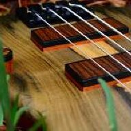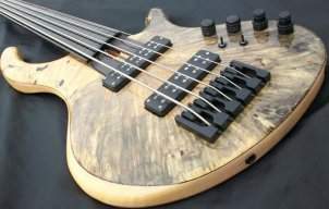
This is a pictorial on how I do my fiber optic side markers. I got to looking around at all of the tutorials on here and decided it was about time ol’ Scotty D started pulling his own weight! Feel free to ask any questions and disregard the poor grammer.
I get a few emails asking how fiber optic side markers compare to LED’s. I've owned and installed both and both are great, the cost of material is about the same. It comes down to personal preference and I prefer the Fibers for these reasons.
Fibers are easier to install. They use only a single light source, so you can light the entire fingerboard using just a single LED. Since you’re only using one LED your battery life is much longer than using multiple LED’s. The fibers will last a lifetime. This is the same material communication companies put in the ground for high bandwidth telephone lines. They won't burn out and they don’t require any wiring or resistors to work. You mount your LED and it's wiring in the control cavity where it’s easily accessible. Since you’re using only one LED mounted in the control cavity if you ever grow tired of the color of you side markers or if the LED burns out you can simply change the LED just as you would a house bulb. My main gripe against LED’s in the fingerboard is that if the bulbs, resistors, wiring or solder joints fail you have to remove the fingerboard to repair it. If this happens those little luxury lights have officially became a pain in the butt. Although a good installed set of LED’s should last a long time, with all of those electrical connections and components Murphy’s Law has to come to mind. Enough of my ranting on this! On to the pictorial!
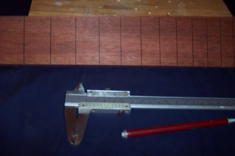
I start by laying out the location of the side markers. I do this just like any side marker except for one difference. I tend to mount the markers a little closer to the bottom edge where the neck and fingerboard join. This will allow more room if the fret slots need to be cut deeper. In other words you won't cut through the fibers. To mark out the markers I use my trusty calipers to locate where I want the markers and a sharp pencil to put a mark at that location. Once all are marked I then take a sharp tipped needle file and push a small indentions where my pencil marks are. These indentions will help in drilling the hole accurately.
Once the markers are laid out I use a pilot point drill bit to drill the holes on my small drill press. The bit I used here is a 9/64" I drilled these holes about 5mm deep.
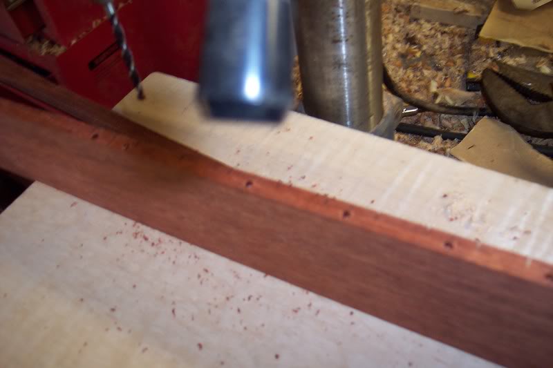
On a router table I take the now drilled fingerboard and route a 3/16" wide channel on the back side of the board. The depth of the channel is the same as the center mark of the marker holes. I put this channel 1/4" from the edge of the finger board. It starts at the 3rd fret marker and stops just past the 24th fret markers. You can put your channel wherever you feel best, just don't put it directly above the truss rod.
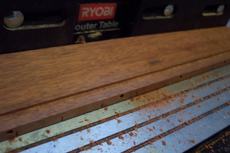
Once I have the main channel routed I move the fence back 1/16" and route again from the 12 fret to the 24th. Then I move the fence back another 1/16" and route from the 17th fret to the 24th. This makes the channel wider as the markers come into it. You may decide to do this different but I've found that the stepped channel allows plenty of room for the fibers to lie on the bottom of the channel and not stacked upon one another.
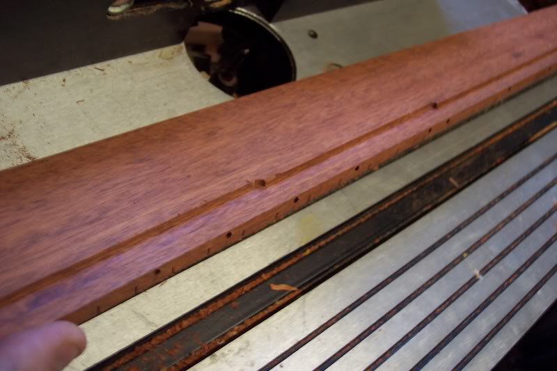
Once the channel is drilled the side marker hole will need to be drilled to meet the channel. I used a 1/6" drill bit chucked into my Dremel to do this. Since I used a pilot bit to drill the bigger hole, the smaller bit centers itself with the divot the pilot bit left.
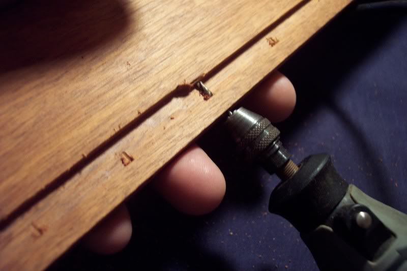
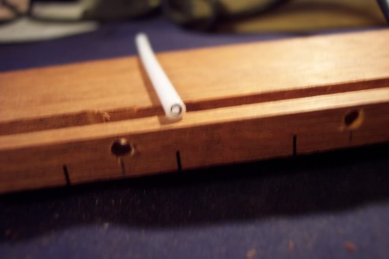
Here is the marker material I am using. I won't tell you where I got it. It would be foolish to tell you all of my secrets. I stumbled across this by accident while enjoying a tasty treat. I'd be a sucker to tell you, so instead I'll be a stick in the mud and make you figure out what it is....Got it yet? If not, too bad for you. This material has a hole running down the center it's entire length. I tried to mark the hole so it shows up better in the picture. The fiber will run through this center hole. I started doing this for one simple reason when the fibers are not lit up you will still have a marker to go by. Most of my other fiber basses only have the fiber by themselves so no light, no markers. This way is more user friendly.
This mysterious marker material installs just like any other old plastic material. I cut the marker and file flat the side that is going in the hole. I glue mine in with a little bit of CA, be careful and don’t get any glue on the bottom or top of the marker where the center hole is, you want to try to keep that hole open.
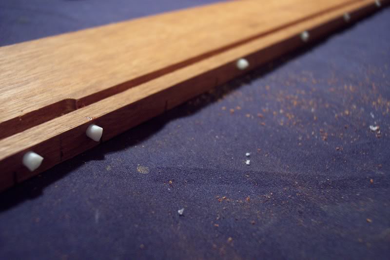
Once the markers are installed and the ca has setup I take the board to my bench top belt sander. With a fine 180-grit belt I surface the markers to the board. If you go about this slowly you wont have any issues with the markers getting heated up and melting, you could also just use a file or sanding block.
Now it’s time to make the magic happen. The fiber I am using here is .75mm. I run the fibers trough the center of the plastic marker and into the channel. I run them from the marker to the end of the board and add 16" extra to make sure there is plenty to travel through the body and into the control cavity. I also like to leave about 3/8" exposed on the marker side. I do this so I can see the fiber easy and so I can level it with marker later. Here you can see the fiber going through the marker and making a 90 bend to run down the channel. See how the bend is gradual, this will not affect the light transfer in the fiber, if you bent the fiber too abrupt it can diminish the amount of light that travels through it.
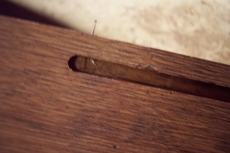
I string the fibers through the board in into the channel and as I go I use a little masking tape to hold fibers down. This is just temporary, once held down with the tape I mix a little epoxy and drip it into the channel to hold the fibers down for good. DO NOT USE CA GLUE ON FIBERS, it melts them. I learned this a while back the hard way.
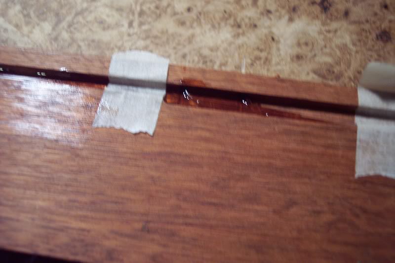
Like I said I like to tape and glue as I go. Keeping the fibers in place can be a bit tricky so it's much easier to tape and glue them down as you go, rather than install them all and tape/glue them afterward
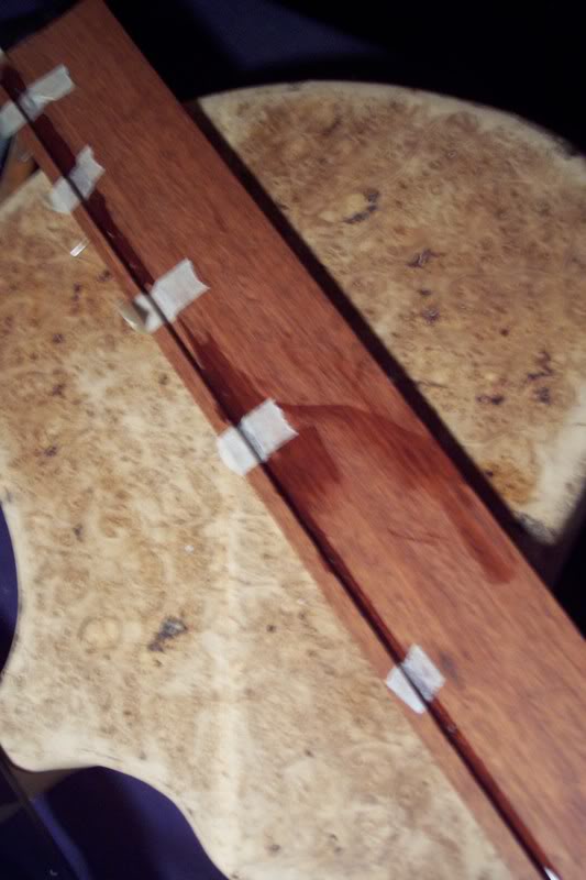
Here is where the fibers collect at the end of the board. I like to tape them all together at this point and leave them like so until the epoxy sets.
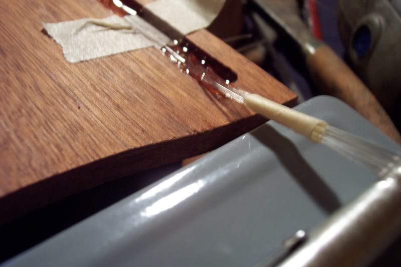
I remove all of the tape and fill the channel all the way with epoxy. Now the fibers are set for good. You can do this many different ways. I've used sawdust and wood glue before too which works well but I think epoxy is better. The main thing is that the channel is filled so you get all of your gluing surface back.
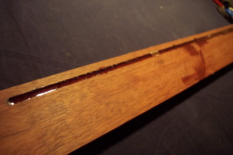
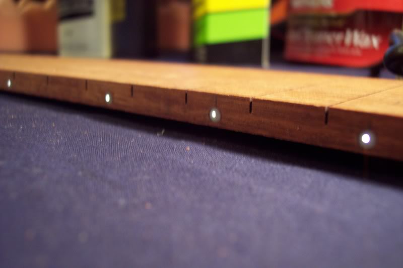
Once all of the epoxy has cured I level the fibers with the plastic markers and I now have this.
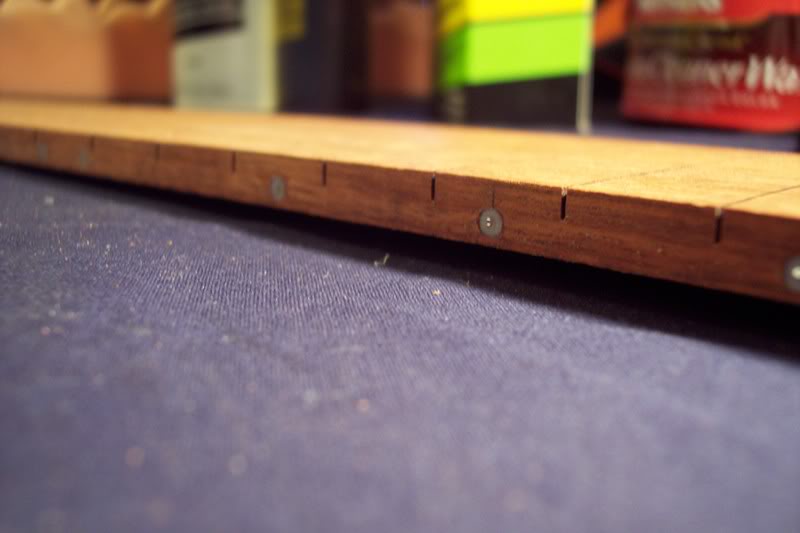
Put a light source to the end of the fibers and I now have this. Instant fun!
This is as far as I will go today. In part 2 I will show you how to run the fibers through the bass and into the cavity. I’ll also show how to wire the LED light source and connect it with the fibers. STAY TUNED!
Oh almost forgot, here are the places you can buy this stuff.
Invalid Link Removed
Invalid Link Removed Maybe you've guessed the mystery material by now?
Feel free to ask any questions and disregard the poor grammer.I get a few emails asking how fiber optic side markers compare to LED’s. I've owned and installed both and both are great, the cost of material is about the same. It comes down to personal preference and I prefer the Fibers for these reasons.
Fibers are easier to install. They use only a single light source, so you can light the entire fingerboard using just a single LED. Since you’re only using one LED your battery life is much longer than using multiple LED’s. The fibers will last a lifetime. This is the same material communication companies put in the ground for high bandwidth telephone lines. They won't burn out and they don’t require any wiring or resistors to work. You mount your LED and it's wiring in the control cavity where it’s easily accessible. Since you’re using only one LED mounted in the control cavity if you ever grow tired of the color of you side markers or if the LED burns out you can simply change the LED just as you would a house bulb. My main gripe against LED’s in the fingerboard is that if the bulbs, resistors, wiring or solder joints fail you have to remove the fingerboard to repair it. If this happens those little luxury lights have officially became a pain in the butt. Although a good installed set of LED’s should last a long time, with all of those electrical connections and components Murphy’s Law has to come to mind.
Enough of my ranting on this! On to the pictorial!I start by laying out the location of the side markers. I do this just like any side marker except for one difference. I tend to mount the markers a little closer to the bottom edge where the neck and fingerboard join. This will allow more room if the fret slots need to be cut deeper. In other words you won't cut through the fibers.
To mark out the markers I use my trusty calipers to locate where I want the markers and a sharp pencil to put a mark at that location. Once all are marked I then take a sharp tipped needle file and push a small indentions where my pencil marks are. These indentions will help in drilling the hole accurately.Once the markers are laid out I use a pilot point drill bit to drill the holes on my small drill press. The bit I used here is a 9/64" I drilled these holes about 5mm deep.
On a router table I take the now drilled fingerboard and route a 3/16" wide channel on the back side of the board. The depth of the channel is the same as the center mark of the marker holes. I put this channel 1/4" from the edge of the finger board. It starts at the 3rd fret marker and stops just past the 24th fret markers. You can put your channel wherever you feel best, just don't put it directly above the truss rod.
Once I have the main channel routed I move the fence back 1/16" and route again from the 12 fret to the 24th. Then I move the fence back another 1/16" and route from the 17th fret to the 24th. This makes the channel wider as the markers come into it. You may decide to do this different but I've found that the stepped channel allows plenty of room for the fibers to lie on the bottom of the channel and not stacked upon one another.
Once the channel is drilled the side marker hole will need to be drilled to meet the channel. I used a 1/6" drill bit chucked into my Dremel to do this. Since I used a pilot bit to drill the bigger hole, the smaller bit centers itself with the divot the pilot bit left.
Here is the marker material I am using. I won't tell you where I got it. It would be foolish to tell you all of my secrets. I stumbled across this by accident while enjoying a tasty treat. I'd be a sucker to tell you, so instead I'll be a stick in the mud and make you figure out what it is....Got it yet? If not, too bad for you.
This material has a hole running down the center it's entire length. I tried to mark the hole so it shows up better in the picture. The fiber will run through this center hole. I started doing this for one simple reason when the fibers are not lit up you will still have a marker to go by. Most of my other fiber basses only have the fiber by themselves so no light, no markers. This way is more user friendly.This mysterious marker material installs just like any other old plastic material. I cut the marker and file flat the side that is going in the hole. I glue mine in with a little bit of CA, be careful and don’t get any glue on the bottom or top of the marker where the center hole is, you want to try to keep that hole open.
Once the markers are installed and the ca has setup I take the board to my bench top belt sander. With a fine 180-grit belt I surface the markers to the board. If you go about this slowly you wont have any issues with the markers getting heated up and melting, you could also just use a file or sanding block.
Now it’s time to make the magic happen. The fiber I am using here is .75mm. I run the fibers trough the center of the plastic marker and into the channel. I run them from the marker to the end of the board and add 16" extra to make sure there is plenty to travel through the body and into the control cavity. I also like to leave about 3/8" exposed on the marker side. I do this so I can see the fiber easy and so I can level it with marker later. Here you can see the fiber going through the marker and making a 90 bend to run down the channel. See how the bend is gradual, this will not affect the light transfer in the fiber, if you bent the fiber too abrupt it can diminish the amount of light that travels through it.
I string the fibers through the board in into the channel and as I go I use a little masking tape to hold fibers down. This is just temporary, once held down with the tape I mix a little epoxy and drip it into the channel to hold the fibers down for good. DO NOT USE CA GLUE ON FIBERS, it melts them. I learned this a while back the hard way.
Like I said I like to tape and glue as I go. Keeping the fibers in place can be a bit tricky so it's much easier to tape and glue them down as you go, rather than install them all and tape/glue them afterward
Here is where the fibers collect at the end of the board. I like to tape them all together at this point and leave them like so until the epoxy sets.
I remove all of the tape and fill the channel all the way with epoxy. Now the fibers are set for good. You can do this many different ways. I've used sawdust and wood glue before too which works well but I think epoxy is better. The main thing is that the channel is filled so you get all of your gluing surface back.
Once all of the epoxy has cured I level the fibers with the plastic markers and I now have this.
Put a light source to the end of the fibers and I now have this. Instant fun!
This is as far as I will go today. In part 2 I will show you how to run the fibers through the bass and into the cavity. I’ll also show how to wire the LED light source and connect it with the fibers. STAY TUNED!
Oh almost forgot, here are the places you can buy this stuff.
Invalid Link Removed
Invalid Link Removed Maybe you've guessed the mystery material by now?