

Enjoy the benefits of a premium membership!
Upgrade Account
-
TalkBass has been independent since 1998. Add your voice.
Create a free account to reply to discussions, view embedded media, and browse with fewer display ads.
Join free Log in
Want zero display ads or expanded classifieds tools? Compare plans.
You are using an out of date browser. It may not display this or other websites correctly.
You should upgrade or use an alternative browser.
You should upgrade or use an alternative browser.
I 3D printed a bass!
- Thread starter MrCoolsville
- Start date
More options
Who Replied?
3d printed guitar body: Search Result | eBay
Still a fun project. It kind of shows that perhaps someday a person may have a "fabricator" at home and buy plans for all kinds of things off Amazon that print out at your home. A glimpse of the future.
Still a fun project. It kind of shows that perhaps someday a person may have a "fabricator" at home and buy plans for all kinds of things off Amazon that print out at your home. A glimpse of the future.
As an eBay Associate, TalkBass may earn a commission from qualifying purchases.

Are you taking orders?
I hadn't seriously considered it, but it appears KJMO found someone on eBay doing just that. See the post above here!

The listing doesn't mention reinforcements. The thing will break as soon as you put string tension on it if it doesn't have some kind of reinforcement. Definitely know what you are getting into before purchasing.I hadn't seriously considered it, but it appears KJMO found someone on eBay doing just that. See the post above here!

Good on ya' for attempting this project.
LOVE the Christmas Story leg lamp analogy.
LOVE the Christmas Story leg lamp analogy.


3D printed bass guitar - tone demo - YouTube
View attachment 4641206
Quick stats
Note that these prices were as of Jan 29, 2022, and these links will probably break over time.
Printing the body was fairly straight-forward. I found the following two models by EG3DPrinting and zerink for the body and pickguard, respectively:
Hexagonal Precision Bass Guitar by EG3Dprinting
P-BASS pick guard
The body is split into six parts with printed dowls and rectangular inserts to help with alignment and a little bit of rigidity. On my printer, however - a Creality CR-10S Pro V2 - I think I could have printed the body in just two parts: the top and bottom. I didn't realize this until after I was well into the process, though, so I stuck with the original plan. For the majority of the parts, I set layer height to 0.2mm and infill to 20% on a standard 0.4mm nozzle. However, I added a couple of reinforced areas with infill set to 70%: the neck and bridge mounting points. This turned out to be a great decision for adding the steel spine later on. I used the filament noted in the parts list - a PLA+ from Overture - in this amazing "Digital Blue" color. Total print time was around a week running 24 hours a day.
I did run into a small snag printing the left side parts with the hexagon pattern. I originally printed the bottom left piece laying flat as shown in the picture below, but the outside edge was really rough because I added some supports and they didn't come off cleanly. I ultimately reprinted it standing straight up on the inside edge of the part. This gave me a much cleaner print. The middle left was also printed on its inside edge and the top left was printed on its bottom edge (to avoid a big overhang from the horn). I only needed to add minimal supports to these and that did NOT include any supports in the hexagons. But they still printed nicely, just as I had hoped!
The pickguard was straight-forward and printed out in two pieces. There was no way for me to easily orient the entire thing to print in one piece on my printer. So, I settled on two pieces and used a combination of super glue and copper tape on the back to close up the seam.
View attachment 4641207 View attachment 4641215
Assembling the body
I chose the 2-part epoxy by Gorilla to bind the parts together. Using two bigass clamps, I first glued the left and right side of each section (bottom, middle, and top) and let them dry overnight. Then, I glued all three pieces together and let that dry overnight. At this point, the body was fully assembled, but still required a LOT of work. The third picture here shows everything together with the pickguard laying on top. To be honest, it was only at this point that I knew the pickguard would actually fit. Remember, the models came from different people on different websites!
View attachment 4641216 View attachment 4641217 View attachment 4641218
Sanding
This is the part that took the most labor and personal time. My first task was to try hiding all the seams between the six printed parts. I used this ProBond filler from Elmer's that I heard good things about for 3D printing. I just used my finger to liberally glob it on all the seams and let it dry for a few hours.
View attachment 4641219 View attachment 4641220
Then I went to sanding to both smooth out the filler and remove most of the print lines. I started by using some 80 grit sand paper on a hand sander.
View attachment 4641224
It didn't take long to realize how much of a pain it would be to hand sand the whole thing, so I went with my orbital sander instead. That made things MUCH faster and easier. I was able to knock down pretty much all the print lines and smooth out the seams, and it was looking pretty good after a couple rounds of filling, sanding, filling again, and sanding again. Of course, I got to finer and finer grit as I went.
View attachment 4641225 View attachment 4641226
I then started the priming process. I didn't seem to get many pictures here, but I went back and forth between priming, sanding, priming some more, and sanding some more. At the end of it all, the whole body was white and looked pretty damn smooth. I thought the seams were gone, but as you can see in the final product, that wasn't really the case.
Painting
My original plan was to let the blue of the filament remain naked in the hexagons and paint the rest of the body satin black. However, I quickly realized how painful it would be to try taping off the hexagons to keep them pristine while sanding and painting all around them. I ultimately decided to just paint the whole thing black and then come back around and re-paint the hexagons to a blue paint that would closely match the original filament color. I went with a "Sail Blue" color paint I found at Home Depot for a few bucks.
To make it easier to paint, I installed a screw into one of the neck screw holes and hung the body while I painted. The pickguard was just laid down on a piece of cardboard. And it's worth noting that I also painted the headstock black to match the body.
View attachment 4641229 View attachment 4641231 View attachment 4641237
After painting everything black, I taped off most of the body and came back around with the blue.
View attachment 4641233 View attachment 4641234 View attachment 4641235 View attachment 4641236
While paint was drying, I also took the model for the body and took a tiny slice of the hexagon pattern. I then just printed that slice to use for a little flair on the headstock. I painted that the same blue, although the dim yellow lighting in this pic makes the color all wonky.
View attachment 4641238
Ultimately, I did three lighter coats of black/blue and two coats of clear. For the pickguard, I went back with a fine paint brush and added the blue outline to the edges. Here is everything laid together after the paint had dried:
View attachment 4641239
Electronics
I started into the electronics by lining everything with copper shielding tape I had laying around.
View attachment 4641241 View attachment 4641242 View attachment 4641243
I then got everything wired and soldered up. Note the copper tape to hold down and provide a larger contact area for the bridge ground wire. I don't have a pic of it, but I later discovered a problem there because the black paint on the bridge prevented good contact with the copper. A quick scouring with my Dremel fixed that issue.
View attachment 4641245
And this is where I ran into my first major snag. When I went to drop the pickguard down, I realized the pots were too wide to fit into the control cavity. My solution was to use my Dremel to bore out some space for the pots.
View attachment 4641244
After fiddling a bunch with the electronics and placement of the pickguard, I was finally happy and moved on to mounting the bridge and neck. This is where I ran into my second major snag. I drilled in the screws to mount the neck, but then had to remove them for some reason (I don't even remember why now). When I did this, the friction of the screws going through the PLA must have melted the material. This basically locked the screws into place. I realized this as I tried to back out the screws. The head of one snapped and I thought it was a fluke. And then a second screw head snapped.
My first idea was to try using a broken screw backout kit, but that did nothing but make the remaining part of the screw completely inaccessible. I gave up on that screw. For the second broken screw, I had the great idea of using my soldering iron to heat the screw up to soften the plastic, and then using some channel locks to back it out. That worked perfectly and I was able to remove one of the broken screws and the remaining intact screw with no problem. But that left me with one screw still stuck, which I ultimately just left in place. I just drilled a new hole into the body, plate, and neck and ignored the broken one.
View attachment 4641246 View attachment 4641247 View attachment 4641248
Final assembly (or so I thought)
After getting around the broken screw issue and securely mounting the neck, the only thing left was to get the tuners on, install the strap buttons, and string it up. No drama here, the tuners and buttons went on just fine and the body seemed to hold as I got the strings on.
View attachment 4641253
Catastrophe!
Once everything was together and I tuned up the bass, I noticed the string height was pretty bad. No worries, I'll just do a proper setup... right? Well, as I began to tighten the truss rod nut, tragedy struck. The bass snapped in half in my hands.
View attachment 4641255
One of the seams failed. Amazingly, though, the printed pieces themselves seemed to be holding up just fine. But as you can imagine, I was horrified. I felt like the dad in A Christmas Story when his freshly glued leg lamp crumpled into his arms. So, after setting the bass down and calling it a night, I did some thinking on how to solve this third and final major snag. My solution was to mount a 1/8" thick piece of steel to the back of the bass. The piece I bought from Home Depot was 2" wide and 36" long; plenty to work with.
After re-gluing the body back together, I cut the steel piece to size and went about mounting it. I went with four screws through both ends of the bass, with the four at the neck reusing the neck mounting screws. In fact, the steel spine replaced the neck plate altogether. Fortunately, I had increased the infill of the print in a big block where the bridge mounts, so that entire area was strengthened and provided a great place to screw in the spine.
View attachment 4641256
Before doing any further painting to hide the spine, I reassembled the bass and tested everything out. It's been holding strong for well over a week now, so I'm confident that the spine will do its job! I did have a few issues with the electronics making some buzzing noises, but some troubleshooting of my shielding job was all that was needed. She plays smoothly and noise-free now! And after feeling confident that the spine would hold, I went back and painted the back of the bass again. All-in-all, the spine added about 1.1lbs of weight to the body.
View attachment 4641258
Playability and final thoughts
Overall, I'm super happy with how the project turned out. I've never built my own bass before and this was, by far, the most complex 3D printing project I've taken on so far. Coming in at about 9.4lbs, it does feel just a hair on the heavier side for a 4-string P-bass. And it had some significant neck dive before I installed the steel spine. But the added weight of the spine had the hidden benefit of balancing out the weight of the bass, and now it sits perfectly still on my leg or from a strap.
The neck, while super cheap, feels surprisingly good. It's made out of Canadian maple and has a great flat/satin finish. There are no sharp frets and the leveling seems good so far. I was even able to get my string action pretty low. I would have preferred a little bit of a different headstock shape - it's huge and the weight of the tuners is really far out, contributing to the neck dive it used to have - but I guess it works in this classic styling. Oh, and this is now the only bass I have with a truss rod adjustment at the headstock. Thanks, I hate it. Give me a heel adjustment point any day of the week!
The sound of this thing is surprisingly good. It's unbelievable how cheap the electronics are, and yet it sounds... well, like a passive P-bass should. I didn't put it in the video, but playing with a pick sounds great, as does really digging in for some percussive playing (think Flea). I won't say slap sounds great on it, but hey, it's a P-bass.
For 300 bucks, having a completely unique instrument is pretty cool. And I don't think this will be the last bass I 3D print. I already have ideas floating around for a 5-string, but this time I'm going to design the body myself. I'm thinking two Stingray/G&L-style humbuckers with active pickups and electronics, a body shape that looks nothing like what's available today, and higher quality parts all around. I think I might build the steel spine into the model, too. It helped immensely with rigidity, and I bet I could get away with reducing the infill even further for most of the body to reduce filament used and overall weight. I'll also take a different approach for covering seams since that didn't turn out all that great in this project. My father-in-law is a carpenter and already has some great ideas for me there.
If/when the day comes that I do another project, I'll be sure to spin up another thread about it. Until then, let me know what you think about this one![/QUOTE]
This is awesome! Great job.
View attachment 4641206
Quick stats
- Fully passive
- Fender Precision-style body
- Single split coil pickup
- 34" scale
- 3D printed body made from PLA+
- Printed in 6 pieces and bound together
- Steel reinforcement spine (more on that later)
- Maple neck with composite ebony fretboard
- 9.4 lbs
- Total cost of materials was around $300 USD after tax
Note that these prices were as of Jan 29, 2022, and these links will probably break over time.
- Metallor bridge - $15
- Metallor tuners - $19
- BexGears neck - $66
- Dopro neck plate - later replaced with the steel spine, so price not counted
- Wilkinson P-bass humbucker pickup - $19
- Generic wiring harness kit - $16
- Vintage Forge knobs - $13
- Vintage Force strap buttons - $8
- Overture PLA+ filament x 2 - $44
- Ernie Ball Regular Slinky strings - $20
- Gorilla epoxy - $13
- Dupli-Color primer - $14
- SEM Paints satin black paint - $19
- Krylon satin crystal clear coat - $5
- Pickguard screws - $6
- Total: $277 USD + tax
Printing the body was fairly straight-forward. I found the following two models by EG3DPrinting and zerink for the body and pickguard, respectively:
Hexagonal Precision Bass Guitar by EG3Dprinting
P-BASS pick guard
The body is split into six parts with printed dowls and rectangular inserts to help with alignment and a little bit of rigidity. On my printer, however - a Creality CR-10S Pro V2 - I think I could have printed the body in just two parts: the top and bottom. I didn't realize this until after I was well into the process, though, so I stuck with the original plan. For the majority of the parts, I set layer height to 0.2mm and infill to 20% on a standard 0.4mm nozzle. However, I added a couple of reinforced areas with infill set to 70%: the neck and bridge mounting points. This turned out to be a great decision for adding the steel spine later on. I used the filament noted in the parts list - a PLA+ from Overture - in this amazing "Digital Blue" color. Total print time was around a week running 24 hours a day.
I did run into a small snag printing the left side parts with the hexagon pattern. I originally printed the bottom left piece laying flat as shown in the picture below, but the outside edge was really rough because I added some supports and they didn't come off cleanly. I ultimately reprinted it standing straight up on the inside edge of the part. This gave me a much cleaner print. The middle left was also printed on its inside edge and the top left was printed on its bottom edge (to avoid a big overhang from the horn). I only needed to add minimal supports to these and that did NOT include any supports in the hexagons. But they still printed nicely, just as I had hoped!
The pickguard was straight-forward and printed out in two pieces. There was no way for me to easily orient the entire thing to print in one piece on my printer. So, I settled on two pieces and used a combination of super glue and copper tape on the back to close up the seam.
View attachment 4641207 View attachment 4641215
Assembling the body
I chose the 2-part epoxy by Gorilla to bind the parts together. Using two bigass clamps, I first glued the left and right side of each section (bottom, middle, and top) and let them dry overnight. Then, I glued all three pieces together and let that dry overnight. At this point, the body was fully assembled, but still required a LOT of work. The third picture here shows everything together with the pickguard laying on top. To be honest, it was only at this point that I knew the pickguard would actually fit. Remember, the models came from different people on different websites!
View attachment 4641216 View attachment 4641217 View attachment 4641218
Sanding
This is the part that took the most labor and personal time. My first task was to try hiding all the seams between the six printed parts. I used this ProBond filler from Elmer's that I heard good things about for 3D printing. I just used my finger to liberally glob it on all the seams and let it dry for a few hours.
View attachment 4641219 View attachment 4641220
Then I went to sanding to both smooth out the filler and remove most of the print lines. I started by using some 80 grit sand paper on a hand sander.
View attachment 4641224
It didn't take long to realize how much of a pain it would be to hand sand the whole thing, so I went with my orbital sander instead. That made things MUCH faster and easier. I was able to knock down pretty much all the print lines and smooth out the seams, and it was looking pretty good after a couple rounds of filling, sanding, filling again, and sanding again. Of course, I got to finer and finer grit as I went.
View attachment 4641225 View attachment 4641226
I then started the priming process. I didn't seem to get many pictures here, but I went back and forth between priming, sanding, priming some more, and sanding some more. At the end of it all, the whole body was white and looked pretty damn smooth. I thought the seams were gone, but as you can see in the final product, that wasn't really the case.
Painting
My original plan was to let the blue of the filament remain naked in the hexagons and paint the rest of the body satin black. However, I quickly realized how painful it would be to try taping off the hexagons to keep them pristine while sanding and painting all around them. I ultimately decided to just paint the whole thing black and then come back around and re-paint the hexagons to a blue paint that would closely match the original filament color. I went with a "Sail Blue" color paint I found at Home Depot for a few bucks.
To make it easier to paint, I installed a screw into one of the neck screw holes and hung the body while I painted. The pickguard was just laid down on a piece of cardboard. And it's worth noting that I also painted the headstock black to match the body.
View attachment 4641229 View attachment 4641231 View attachment 4641237
After painting everything black, I taped off most of the body and came back around with the blue.
View attachment 4641233 View attachment 4641234 View attachment 4641235 View attachment 4641236
While paint was drying, I also took the model for the body and took a tiny slice of the hexagon pattern. I then just printed that slice to use for a little flair on the headstock. I painted that the same blue, although the dim yellow lighting in this pic makes the color all wonky.
View attachment 4641238
Ultimately, I did three lighter coats of black/blue and two coats of clear. For the pickguard, I went back with a fine paint brush and added the blue outline to the edges. Here is everything laid together after the paint had dried:
View attachment 4641239
Electronics
I started into the electronics by lining everything with copper shielding tape I had laying around.
View attachment 4641241 View attachment 4641242 View attachment 4641243
I then got everything wired and soldered up. Note the copper tape to hold down and provide a larger contact area for the bridge ground wire. I don't have a pic of it, but I later discovered a problem there because the black paint on the bridge prevented good contact with the copper. A quick scouring with my Dremel fixed that issue.
View attachment 4641245
And this is where I ran into my first major snag. When I went to drop the pickguard down, I realized the pots were too wide to fit into the control cavity. My solution was to use my Dremel to bore out some space for the pots.
View attachment 4641244
After fiddling a bunch with the electronics and placement of the pickguard, I was finally happy and moved on to mounting the bridge and neck. This is where I ran into my second major snag. I drilled in the screws to mount the neck, but then had to remove them for some reason (I don't even remember why now). When I did this, the friction of the screws going through the PLA must have melted the material. This basically locked the screws into place. I realized this as I tried to back out the screws. The head of one snapped and I thought it was a fluke. And then a second screw head snapped.
My first idea was to try using a broken screw backout kit, but that did nothing but make the remaining part of the screw completely inaccessible. I gave up on that screw. For the second broken screw, I had the great idea of using my soldering iron to heat the screw up to soften the plastic, and then using some channel locks to back it out. That worked perfectly and I was able to remove one of the broken screws and the remaining intact screw with no problem. But that left me with one screw still stuck, which I ultimately just left in place. I just drilled a new hole into the body, plate, and neck and ignored the broken one.
View attachment 4641246 View attachment 4641247 View attachment 4641248
Final assembly (or so I thought)
After getting around the broken screw issue and securely mounting the neck, the only thing left was to get the tuners on, install the strap buttons, and string it up. No drama here, the tuners and buttons went on just fine and the body seemed to hold as I got the strings on.
View attachment 4641253
Catastrophe!
Once everything was together and I tuned up the bass, I noticed the string height was pretty bad. No worries, I'll just do a proper setup... right? Well, as I began to tighten the truss rod nut, tragedy struck. The bass snapped in half in my hands.
View attachment 4641255
One of the seams failed. Amazingly, though, the printed pieces themselves seemed to be holding up just fine. But as you can imagine, I was horrified. I felt like the dad in A Christmas Story when his freshly glued leg lamp crumpled into his arms. So, after setting the bass down and calling it a night, I did some thinking on how to solve this third and final major snag. My solution was to mount a 1/8" thick piece of steel to the back of the bass. The piece I bought from Home Depot was 2" wide and 36" long; plenty to work with.
After re-gluing the body back together, I cut the steel piece to size and went about mounting it. I went with four screws through both ends of the bass, with the four at the neck reusing the neck mounting screws. In fact, the steel spine replaced the neck plate altogether. Fortunately, I had increased the infill of the print in a big block where the bridge mounts, so that entire area was strengthened and provided a great place to screw in the spine.
View attachment 4641256
Before doing any further painting to hide the spine, I reassembled the bass and tested everything out. It's been holding strong for well over a week now, so I'm confident that the spine will do its job! I did have a few issues with the electronics making some buzzing noises, but some troubleshooting of my shielding job was all that was needed. She plays smoothly and noise-free now! And after feeling confident that the spine would hold, I went back and painted the back of the bass again. All-in-all, the spine added about 1.1lbs of weight to the body.
View attachment 4641258
Playability and final thoughts
Overall, I'm super happy with how the project turned out. I've never built my own bass before and this was, by far, the most complex 3D printing project I've taken on so far. Coming in at about 9.4lbs, it does feel just a hair on the heavier side for a 4-string P-bass. And it had some significant neck dive before I installed the steel spine. But the added weight of the spine had the hidden benefit of balancing out the weight of the bass, and now it sits perfectly still on my leg or from a strap.
The neck, while super cheap, feels surprisingly good. It's made out of Canadian maple and has a great flat/satin finish. There are no sharp frets and the leveling seems good so far. I was even able to get my string action pretty low. I would have preferred a little bit of a different headstock shape - it's huge and the weight of the tuners is really far out, contributing to the neck dive it used to have - but I guess it works in this classic styling. Oh, and this is now the only bass I have with a truss rod adjustment at the headstock. Thanks, I hate it. Give me a heel adjustment point any day of the week!
The sound of this thing is surprisingly good. It's unbelievable how cheap the electronics are, and yet it sounds... well, like a passive P-bass should. I didn't put it in the video, but playing with a pick sounds great, as does really digging in for some percussive playing (think Flea). I won't say slap sounds great on it, but hey, it's a P-bass.
For 300 bucks, having a completely unique instrument is pretty cool. And I don't think this will be the last bass I 3D print. I already have ideas floating around for a 5-string, but this time I'm going to design the body myself. I'm thinking two Stingray/G&L-style humbuckers with active pickups and electronics, a body shape that looks nothing like what's available today, and higher quality parts all around. I think I might build the steel spine into the model, too. It helped immensely with rigidity, and I bet I could get away with reducing the infill even further for most of the body to reduce filament used and overall weight. I'll also take a different approach for covering seams since that didn't turn out all that great in this project. My father-in-law is a carpenter and already has some great ideas for me there.
If/when the day comes that I do another project, I'll be sure to spin up another thread about it. Until then, let me know what you think about this one![/QUOTE]
Well, the body anyway. The neck is real wood and pre-assembled while all the hardware is standard metal. Check out the finished build along with some tone demos here:
3D printed bass guitar - tone demo - YouTube
View attachment 4641206
Quick stats
Parts list
- Fully passive
- Fender Precision-style body
- Single split coil pickup
- 34" scale
- 3D printed body made from PLA+
- Printed in 6 pieces and bound together
- Steel reinforcement spine (more on that later)
- Maple neck with composite ebony fretboard
- 9.4 lbs
- Total cost of materials was around $300 USD after tax
Note that these prices were as of Jan 29, 2022, and these links will probably break over time.
Printing
- Metallor bridge - $15
- Metallor tuners - $19
- BexGears neck - $66
- Dopro neck plate - later replaced with the steel spine, so price not counted
- Wilkinson P-bass humbucker pickup - $19
- Generic wiring harness kit - $16
- Vintage Forge knobs - $13
- Vintage Force strap buttons - $8
- Overture PLA+ filament x 2 - $44
- Ernie Ball Regular Slinky strings - $20
- Gorilla epoxy - $13
- Dupli-Color primer - $14
- SEM Paints satin black paint - $19
- Krylon satin crystal clear coat - $5
- Pickguard screws - $6
- Total: $277 USD + tax
Printing the body was fairly straight-forward. I found the following two models by EG3DPrinting and zerink for the body and pickguard, respectively:
Hexagonal Precision Bass Guitar by EG3Dprinting
P-BASS pick guard
The body is split into six parts with printed dowls and rectangular inserts to help with alignment and a little bit of rigidity. On my printer, however - a Creality CR-10S Pro V2 - I think I could have printed the body in just two parts: the top and bottom. I didn't realize this until after I was well into the process, though, so I stuck with the original plan. For the majority of the parts, I set layer height to 0.2mm and infill to 20% on a standard 0.4mm nozzle. However, I added a couple of reinforced areas with infill set to 70%: the neck and bridge mounting points. This turned out to be a great decision for adding the steel spine later on. I used the filament noted in the parts list - a PLA+ from Overture - in this amazing "Digital Blue" color. Total print time was around a week running 24 hours a day.
I did run into a small snag printing the left side parts with the hexagon pattern. I originally printed the bottom left piece laying flat as shown in the picture below, but the outside edge was really rough because I added some supports and they didn't come off cleanly. I ultimately reprinted it standing straight up on the inside edge of the part. This gave me a much cleaner print. The middle left was also printed on its inside edge and the top left was printed on its bottom edge (to avoid a big overhang from the horn). I only needed to add minimal supports to these and that did NOT include any supports in the hexagons. But they still printed nicely, just as I had hoped!
The pickguard was straight-forward and printed out in two pieces. There was no way for me to easily orient the entire thing to print in one piece on my printer. So, I settled on two pieces and used a combination of super glue and copper tape on the back to close up the seam.
View attachment 4641207 View attachment 4641215
Assembling the body
I chose the 2-part epoxy by Gorilla to bind the parts together. Using two bigass clamps, I first glued the left and right side of each section (bottom, middle, and top) and let them dry overnight. Then, I glued all three pieces together and let that dry overnight. At this point, the body was fully assembled, but still required a LOT of work. The third picture here shows everything together with the pickguard laying on top. To be honest, it was only at this point that I knew the pickguard would actually fit. Remember, the models came from different people on different websites!
View attachment 4641216 View attachment 4641217 View attachment 4641218
Sanding
This is the part that took the most labor and personal time. My first task was to try hiding all the seams between the six printed parts. I used this ProBond filler from Elmer's that I heard good things about for 3D printing. I just used my finger to liberally glob it on all the seams and let it dry for a few hours.
View attachment 4641219 View attachment 4641220
Then I went to sanding to both smooth out the filler and remove most of the print lines. I started by using some 80 grit sand paper on a hand sander.
View attachment 4641224
It didn't take long to realize how much of a pain it would be to hand sand the whole thing, so I went with my orbital sander instead. That made things MUCH faster and easier. I was able to knock down pretty much all the print lines and smooth out the seams, and it was looking pretty good after a couple rounds of filling, sanding, filling again, and sanding again. Of course, I got to finer and finer grit as I went.
View attachment 4641225 View attachment 4641226
I then started the priming process. I didn't seem to get many pictures here, but I went back and forth between priming, sanding, priming some more, and sanding some more. At the end of it all, the whole body was white and looked pretty damn smooth. I thought the seams were gone, but as you can see in the final product, that wasn't really the case.
Painting
My original plan was to let the blue of the filament remain naked in the hexagons and paint the rest of the body satin black. However, I quickly realized how painful it would be to try taping off the hexagons to keep them pristine while sanding and painting all around them. I ultimately decided to just paint the whole thing black and then come back around and re-paint the hexagons to a blue paint that would closely match the original filament color. I went with a "Sail Blue" color paint I found at Home Depot for a few bucks.
To make it easier to paint, I installed a screw into one of the neck screw holes and hung the body while I painted. The pickguard was just laid down on a piece of cardboard. And it's worth noting that I also painted the headstock black to match the body.
View attachment 4641229 View attachment 4641231 View attachment 4641237
After painting everything black, I taped off most of the body and came back around with the blue.
View attachment 4641233 View attachment 4641234 View attachment 4641235 View attachment 4641236
While paint was drying, I also took the model for the body and took a tiny slice of the hexagon pattern. I then just printed that slice to use for a little flair on the headstock. I painted that the same blue, although the dim yellow lighting in this pic makes the color all wonky.
View attachment 4641238
Ultimately, I did three lighter coats of black/blue and two coats of clear. For the pickguard, I went back with a fine paint brush and added the blue outline to the edges. Here is everything laid together after the paint had dried:
View attachment 4641239
Electronics
I started into the electronics by lining everything with copper shielding tape I had laying around.
View attachment 4641241 View attachment 4641242 View attachment 4641243
I then got everything wired and soldered up. Note the copper tape to hold down and provide a larger contact area for the bridge ground wire. I don't have a pic of it, but I later discovered a problem there because the black paint on the bridge prevented good contact with the copper. A quick scouring with my Dremel fixed that issue.
View attachment 4641245
And this is where I ran into my first major snag. When I went to drop the pickguard down, I realized the pots were too wide to fit into the control cavity. My solution was to use my Dremel to bore out some space for the pots.
View attachment 4641244
After fiddling a bunch with the electronics and placement of the pickguard, I was finally happy and moved on to mounting the bridge and neck. This is where I ran into my second major snag. I drilled in the screws to mount the neck, but then had to remove them for some reason (I don't even remember why now). When I did this, the friction of the screws going through the PLA must have melted the material. This basically locked the screws into place. I realized this as I tried to back out the screws. The head of one snapped and I thought it was a fluke. And then a second screw head snapped.
My first idea was to try using a broken screw backout kit, but that did nothing but make the remaining part of the screw completely inaccessible. I gave up on that screw. For the second broken screw, I had the great idea of using my soldering iron to heat the screw up to soften the plastic, and then using some channel locks to back it out. That worked perfectly and I was able to remove one of the broken screws and the remaining intact screw with no problem. But that left me with one screw still stuck, which I ultimately just left in place. I just drilled a new hole into the body, plate, and neck and ignored the broken one.
View attachment 4641246 View attachment 4641247 View attachment 4641248
Final assembly (or so I thought)
After getting around the broken screw issue and securely mounting the neck, the only thing left was to get the tuners on, install the strap buttons, and string it up. No drama here, the tuners and buttons went on just fine and the body seemed to hold as I got the strings on.
View attachment 4641253
Catastrophe!
Once everything was together and I tuned up the bass, I noticed the string height was pretty bad. No worries, I'll just do a proper setup... right? Well, as I began to tighten the truss rod nut, tragedy struck. The bass snapped in half in my hands.
View attachment 4641255
One of the seams failed. Amazingly, though, the printed pieces themselves seemed to be holding up just fine. But as you can imagine, I was horrified. I felt like the dad in A Christmas Story when his freshly glued leg lamp crumpled into his arms. So, after setting the bass down and calling it a night, I did some thinking on how to solve this third and final major snag. My solution was to mount a 1/8" thick piece of steel to the back of the bass. The piece I bought from Home Depot was 2" wide and 36" long; plenty to work with.
After re-gluing the body back together, I cut the steel piece to size and went about mounting it. I went with four screws through both ends of the bass, with the four at the neck reusing the neck mounting screws. In fact, the steel spine replaced the neck plate altogether. Fortunately, I had increased the infill of the print in a big block where the bridge mounts, so that entire area was strengthened and provided a great place to screw in the spine.
View attachment 4641256
Before doing any further painting to hide the spine, I reassembled the bass and tested everything out. It's been holding strong for well over a week now, so I'm confident that the spine will do its job! I did have a few issues with the electronics making some buzzing noises, but some troubleshooting of my shielding job was all that was needed. She plays smoothly and noise-free now! And after feeling confident that the spine would hold, I went back and painted the back of the bass again. All-in-all, the spine added about 1.1lbs of weight to the body.
View attachment 4641258
Playability and final thoughts
Overall, I'm super happy with how the project turned out. I've never built my own bass before and this was, by far, the most complex 3D printing project I've taken on so far. Coming in at about 9.4lbs, it does feel just a hair on the heavier side for a 4-string P-bass. And it had some significant neck dive before I installed the steel spine. But the added weight of the spine had the hidden benefit of balancing out the weight of the bass, and now it sits perfectly still on my leg or from a strap.
The neck, while super cheap, feels surprisingly good. It's made out of Canadian maple and has a great flat/satin finish. There are no sharp frets and the leveling seems good so far. I was even able to get my string action pretty low. I would have preferred a little bit of a different headstock shape - it's huge and the weight of the tuners is really far out, contributing to the neck dive it used to have - but I guess it works in this classic styling. Oh, and this is now the only bass I have with a truss rod adjustment at the headstock. Thanks, I hate it. Give me a heel adjustment point any day of the week!
The sound of this thing is surprisingly good. It's unbelievable how cheap the electronics are, and yet it sounds... well, like a passive P-bass should. I didn't put it in the video, but playing with a pick sounds great, as does really digging in for some percussive playing (think Flea). I won't say slap sounds great on it, but hey, it's a P-bass.
For 300 bucks, having a completely unique instrument is pretty cool. And I don't think this will be the last bass I 3D print. I already have ideas floating around for a 5-string, but this time I'm going to design the body myself. I'm thinking two Stingray/G&L-style humbuckers with active pickups and electronics, a body shape that looks nothing like what's available today, and higher quality parts all around. I think I might build the steel spine into the model, too. It helped immensely with rigidity, and I bet I could get away with reducing the infill even further for most of the body to reduce filament used and overall weight. I'll also take a different approach for covering seams since that didn't turn out all that great in this project. My father-in-law is a carpenter and already has some great ideas for me there.
If/when the day comes that I do another project, I'll be sure to spin up another thread about it. Until then, let me know what you think about this one!
This is awesome! Great job.
As an Amazon Associate, TalkBass may receive commissions from qualifying purchases made via links on this site.

That's a very cool project with a very thorough review, and pictures!
In the future, some ideas:
1) light weight tuners
2) Relatively dense, heavy bridge
(those above for balance)
3) left & right body sides (no 4-piece) - I believe you said it would fit
4) Counter sink the steel bar so it's flush
5) Shoot some Stew Mac paints in aerosol cans
Learn to print a Modulus neck & you'll be even more rocking!
Did you say there was a recording? Love to hear it.

In the future, some ideas:
1) light weight tuners
2) Relatively dense, heavy bridge
(those above for balance)
3) left & right body sides (no 4-piece) - I believe you said it would fit
4) Counter sink the steel bar so it's flush
5) Shoot some Stew Mac paints in aerosol cans
Learn to print a Modulus neck & you'll be even more rocking!
Did you say there was a recording? Love to hear it.
Never mind, found your YouTube.
Very good.
I love the clocks spinning in your composite printing shots!
Very good.
I love the clocks spinning in your composite printing shots!
Wow. You have way more patience than I, my friend. Much respect. I'm a pretty old dog, and never thought such technology would be available. Or people wanting/wiling to use it.
Cheers, gotta get up, change the channel and, adjust the antenna.
Cheers, gotta get up, change the channel and, adjust the antenna.

Very nice work and thanks for rhe great write up about it.Well, the body anyway. The neck is real wood and pre-assembled while all the hardware is standard metal. Check out the finished build along with some tone demos here:
3D printed bass guitar - tone demo - YouTube
View attachment 4641206
Quick stats
Parts list
- Fully passive
- Fender Precision-style body
- Single split coil pickup
- 34" scale
- 3D printed body made from PLA+
- Printed in 6 pieces and bound together
- Steel reinforcement spine (more on that later)
- Maple neck with composite ebony fretboard
- 9.4 lbs
- Total cost of materials was around $300 USD after tax
Note that these prices were as of Jan 29, 2022, and these links will probably break over time.
Printing
- Metallor bridge - $15
- Metallor tuners - $19
- BexGears neck - $66
- Dopro neck plate - later replaced with the steel spine, so price not counted
- Wilkinson P-bass humbucker pickup - $19
- Generic wiring harness kit - $16
- Vintage Forge knobs - $13
- Vintage Force strap buttons - $8
- Overture PLA+ filament x 2 - $44
- Ernie Ball Regular Slinky strings - $20
- Gorilla epoxy - $13
- Dupli-Color primer - $14
- SEM Paints satin black paint - $19
- Krylon satin crystal clear coat - $5
- Pickguard screws - $6
- Total: $277 USD + tax
Printing the body was fairly straight-forward. I found the following two models by EG3DPrinting and zerink for the body and pickguard, respectively:
Hexagonal Precision Bass Guitar by EG3Dprinting
P-BASS pick guard
The body is split into six parts with printed dowls and rectangular inserts to help with alignment and a little bit of rigidity. On my printer, however - a Creality CR-10S Pro V2 - I think I could have printed the body in just two parts: the top and bottom. I didn't realize this until after I was well into the process, though, so I stuck with the original plan. For the majority of the parts, I set layer height to 0.2mm and infill to 20% on a standard 0.4mm nozzle. However, I added a couple of reinforced areas with infill set to 70%: the neck and bridge mounting points. This turned out to be a great decision for adding the steel spine later on. I used the filament noted in the parts list - a PLA+ from Overture - in this amazing "Digital Blue" color. Total print time was around a week running 24 hours a day.
I did run into a small snag printing the left side parts with the hexagon pattern. I originally printed the bottom left piece laying flat as shown in the picture below, but the outside edge was really rough because I added some supports and they didn't come off cleanly. I ultimately reprinted it standing straight up on the inside edge of the part. This gave me a much cleaner print. The middle left was also printed on its inside edge and the top left was printed on its bottom edge (to avoid a big overhang from the horn). I only needed to add minimal supports to these and that did NOT include any supports in the hexagons. But they still printed nicely, just as I had hoped!
The pickguard was straight-forward and printed out in two pieces. There was no way for me to easily orient the entire thing to print in one piece on my printer. So, I settled on two pieces and used a combination of super glue and copper tape on the back to close up the seam.
View attachment 4641207 View attachment 4641215
Assembling the body
I chose the 2-part epoxy by Gorilla to bind the parts together. Using two bigass clamps, I first glued the left and right side of each section (bottom, middle, and top) and let them dry overnight. Then, I glued all three pieces together and let that dry overnight. At this point, the body was fully assembled, but still required a LOT of work. The third picture here shows everything together with the pickguard laying on top. To be honest, it was only at this point that I knew the pickguard would actually fit. Remember, the models came from different people on different websites!
View attachment 4641216 View attachment 4641217 View attachment 4641218
Sanding
This is the part that took the most labor and personal time. My first task was to try hiding all the seams between the six printed parts. I used this ProBond filler from Elmer's that I heard good things about for 3D printing. I just used my finger to liberally glob it on all the seams and let it dry for a few hours.
View attachment 4641219 View attachment 4641220
Then I went to sanding to both smooth out the filler and remove most of the print lines. I started by using some 80 grit sand paper on a hand sander.
View attachment 4641224
It didn't take long to realize how much of a pain it would be to hand sand the whole thing, so I went with my orbital sander instead. That made things MUCH faster and easier. I was able to knock down pretty much all the print lines and smooth out the seams, and it was looking pretty good after a couple rounds of filling, sanding, filling again, and sanding again. Of course, I got to finer and finer grit as I went.
View attachment 4641225 View attachment 4641226
I then started the priming process. I didn't seem to get many pictures here, but I went back and forth between priming, sanding, priming some more, and sanding some more. At the end of it all, the whole body was white and looked pretty damn smooth. I thought the seams were gone, but as you can see in the final product, that wasn't really the case.
Painting
My original plan was to let the blue of the filament remain naked in the hexagons and paint the rest of the body satin black. However, I quickly realized how painful it would be to try taping off the hexagons to keep them pristine while sanding and painting all around them. I ultimately decided to just paint the whole thing black and then come back around and re-paint the hexagons to a blue paint that would closely match the original filament color. I went with a "Sail Blue" color paint I found at Home Depot for a few bucks.
To make it easier to paint, I installed a screw into one of the neck screw holes and hung the body while I painted. The pickguard was just laid down on a piece of cardboard. And it's worth noting that I also painted the headstock black to match the body.
View attachment 4641229 View attachment 4641231 View attachment 4641237
After painting everything black, I taped off most of the body and came back around with the blue.
View attachment 4641233 View attachment 4641234 View attachment 4641235 View attachment 4641236
While paint was drying, I also took the model for the body and took a tiny slice of the hexagon pattern. I then just printed that slice to use for a little flair on the headstock. I painted that the same blue, although the dim yellow lighting in this pic makes the color all wonky.
View attachment 4641238
Ultimately, I did three lighter coats of black/blue and two coats of clear. For the pickguard, I went back with a fine paint brush and added the blue outline to the edges. Here is everything laid together after the paint had dried:
View attachment 4641239
Electronics
I started into the electronics by lining everything with copper shielding tape I had laying around.
View attachment 4641241 View attachment 4641242 View attachment 4641243
I then got everything wired and soldered up. Note the copper tape to hold down and provide a larger contact area for the bridge ground wire. I don't have a pic of it, but I later discovered a problem there because the black paint on the bridge prevented good contact with the copper. A quick scouring with my Dremel fixed that issue.
View attachment 4641245
And this is where I ran into my first major snag. When I went to drop the pickguard down, I realized the pots were too wide to fit into the control cavity. My solution was to use my Dremel to bore out some space for the pots.
View attachment 4641244
After fiddling a bunch with the electronics and placement of the pickguard, I was finally happy and moved on to mounting the bridge and neck. This is where I ran into my second major snag. I drilled in the screws to mount the neck, but then had to remove them for some reason (I don't even remember why now). When I did this, the friction of the screws going through the PLA must have melted the material. This basically locked the screws into place. I realized this as I tried to back out the screws. The head of one snapped and I thought it was a fluke. And then a second screw head snapped.
My first idea was to try using a broken screw backout kit, but that did nothing but make the remaining part of the screw completely inaccessible. I gave up on that screw. For the second broken screw, I had the great idea of using my soldering iron to heat the screw up to soften the plastic, and then using some channel locks to back it out. That worked perfectly and I was able to remove one of the broken screws and the remaining intact screw with no problem. But that left me with one screw still stuck, which I ultimately just left in place. I just drilled a new hole into the body, plate, and neck and ignored the broken one.
View attachment 4641246 View attachment 4641247 View attachment 4641248
Final assembly (or so I thought)
After getting around the broken screw issue and securely mounting the neck, the only thing left was to get the tuners on, install the strap buttons, and string it up. No drama here, the tuners and buttons went on just fine and the body seemed to hold as I got the strings on.
View attachment 4641253
Catastrophe!
Once everything was together and I tuned up the bass, I noticed the string height was pretty bad. No worries, I'll just do a proper setup... right? Well, as I began to tighten the truss rod nut, tragedy struck. The bass snapped in half in my hands.
View attachment 4641255
One of the seams failed. Amazingly, though, the printed pieces themselves seemed to be holding up just fine. But as you can imagine, I was horrified. I felt like the dad in A Christmas Story when his freshly glued leg lamp crumpled into his arms. So, after setting the bass down and calling it a night, I did some thinking on how to solve this third and final major snag. My solution was to mount a 1/8" thick piece of steel to the back of the bass. The piece I bought from Home Depot was 2" wide and 36" long; plenty to work with.
After re-gluing the body back together, I cut the steel piece to size and went about mounting it. I went with four screws through both ends of the bass, with the four at the neck reusing the neck mounting screws. In fact, the steel spine replaced the neck plate altogether. Fortunately, I had increased the infill of the print in a big block where the bridge mounts, so that entire area was strengthened and provided a great place to screw in the spine.
View attachment 4641256
Before doing any further painting to hide the spine, I reassembled the bass and tested everything out. It's been holding strong for well over a week now, so I'm confident that the spine will do its job! I did have a few issues with the electronics making some buzzing noises, but some troubleshooting of my shielding job was all that was needed. She plays smoothly and noise-free now! And after feeling confident that the spine would hold, I went back and painted the back of the bass again. All-in-all, the spine added about 1.1lbs of weight to the body.
View attachment 4641258
Playability and final thoughts
Overall, I'm super happy with how the project turned out. I've never built my own bass before and this was, by far, the most complex 3D printing project I've taken on so far. Coming in at about 9.4lbs, it does feel just a hair on the heavier side for a 4-string P-bass. And it had some significant neck dive before I installed the steel spine. But the added weight of the spine had the hidden benefit of balancing out the weight of the bass, and now it sits perfectly still on my leg or from a strap.
The neck, while super cheap, feels surprisingly good. It's made out of Canadian maple and has a great flat/satin finish. There are no sharp frets and the leveling seems good so far. I was even able to get my string action pretty low. I would have preferred a little bit of a different headstock shape - it's huge and the weight of the tuners is really far out, contributing to the neck dive it used to have - but I guess it works in this classic styling. Oh, and this is now the only bass I have with a truss rod adjustment at the headstock. Thanks, I hate it. Give me a heel adjustment point any day of the week!
The sound of this thing is surprisingly good. It's unbelievable how cheap the electronics are, and yet it sounds... well, like a passive P-bass should. I didn't put it in the video, but playing with a pick sounds great, as does really digging in for some percussive playing (think Flea). I won't say slap sounds great on it, but hey, it's a P-bass.
For 300 bucks, having a completely unique instrument is pretty cool. And I don't think this will be the last bass I 3D print. I already have ideas floating around for a 5-string, but this time I'm going to design the body myself. I'm thinking two Stingray/G&L-style humbuckers with active pickups and electronics, a body shape that looks nothing like what's available today, and higher quality parts all around. I think I might build the steel spine into the model, too. It helped immensely with rigidity, and I bet I could get away with reducing the infill even further for most of the body to reduce filament used and overall weight. I'll also take a different approach for covering seams since that didn't turn out all that great in this project. My father-in-law is a carpenter and already has some great ideas for me there.
If/when the day comes that I do another project, I'll be sure to spin up another thread about it. Until then, let me know what you think about this one!
And... I've always been a fan of tone plastic. You've settled the tone wood debate forever.
As an Amazon Associate, TalkBass may receive commissions from qualifying purchases made via links on this site.

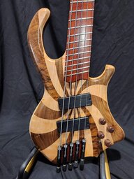
Super cool - you should post this over in the Luthier's Corner, this is the kind of stuff we like over there.
Just to be clear they are using it for product development not so much in manufacturing. 3D printing metal is crazy expensive per part compared to machining and so far is not as accurate. Still a long way to go before we see 3D printing become common for manufacturing. But it is super cool.This is the way basses will be made. Watchmakers have been using 3D printing for years.
Yea, I'm pretty disappointed with the tuners I have now. Definitely the weakest point of the whole build. They're heavy AF, feel terrible to turn, and don't hold their tune very well. For my next project where I put a lot more money into the hardware, I'll definitely go with some Hipshot USAs.That's a very cool project with a very thorough review, and pictures!
In the future, some ideas:
1) light weight tuners
2) Relatively dense, heavy bridge
(those above for balance)
3) left & right body sides (no 4-piece) - I believe you said it would fit
4) Counter sink the steel bar so it's flush
5) Shoot some Stew Mac paints in aerosol cans
Learn to print a Modulus neck & you'll be even more rocking!
Did you say there was a recording? Love to hear it.
Good idea on the heavier bridge. With lightweight tuners, it will help keep the bulk of the weight in the body. And yea, I also will definitely create a placement for the steel bar in the model if I ever use that solution again. I could sink it in, like you said, or I could even create a little insert for it and completely hide it.
I hadn't heard of Stew Mac paints before, but they look to be just the thing I should be using. Thanks for the recommendation!
Super cool - you should post this over in the Luthier's Corner, this is the kind of stuff we like over there.
I thought about it, but I wasn't sure if double posting like that would be frowned upon!

So the tone wood question is now totally settled?
Yes, but the tone filament plastic debate is just getting started!
Glad I could help.Yea, I'm pretty disappointed with the tuners I have now. Definitely the weakest point of the whole build. They're heavy AF, feel terrible to turn, and don't hold their tune very well. For my next project where I put a lot more money into the hardware, I'll definitely go with some Hipshot USAs.
Good idea on the heavier bridge. With lightweight tuners, it will help keep the bulk of the weight in the body. And yea, I also will definitely create a placement for the steel bar in the model if I ever use that solution again. I could sink it in, like you said, or I could even create a little insert for it and completely hide it.
I hadn't heard of Stew Mac paints before, but they look to be just the thing I should be using. Thanks for the recommendation!
I just thought of this: Call Stew Mac before using - be sure they are compatible with your print substrate. They are meant to be used on WOOD.
That is really nice looking.
I am designing one now that I can print in one piece on a 400mm size printer. Total cost for all parts and material is about $150.
Printables
I am designing one now that I can print in one piece on a 400mm size printer. Total cost for all parts and material is about $150.
Printables
Oh dang! Post here when you're done with the model. Maybe I'll print it out and move all my parts over from the original 3D printed bass I made.That is really nice looking.
I am designing one now that I can print in one piece on a 400mm size printer. Total cost for all parts and material is about $150.
Printables
I don't think I mentioned it here before, but last summer while I was on vacation, it got super hot in my studio and the bass body warped a bit. Now, the strings are super high and no measure of removing neck relief or lowering the action at the bridge can compensate for it. It's almost unplayable now.

Learn slide bass, then. I'm not even joking. Make lemonade!Oh dang! Post here when you're done with the model. Maybe I'll print it out and move all my parts over from the original 3D printed bass I made.
I don't think I mentioned it here before, but last summer while I was on vacation, it got super hot in my studio and the bass body warped a bit. Now, the strings are super high and no measure of removing neck relief or lowering the action at the bridge can compensate for it. It's almost unplayable now.


