• TalkBass has been independent since 1998. Add your voice.
    Create a free account to reply to discussions, view embedded media, and browse with fewer display ads.
    Join freeLog in
    Want zero display ads or expanded classifieds tools? Compare plans.

Let's build a tube preamp

Oct 18, 2015
6,558
12,256
SoCal
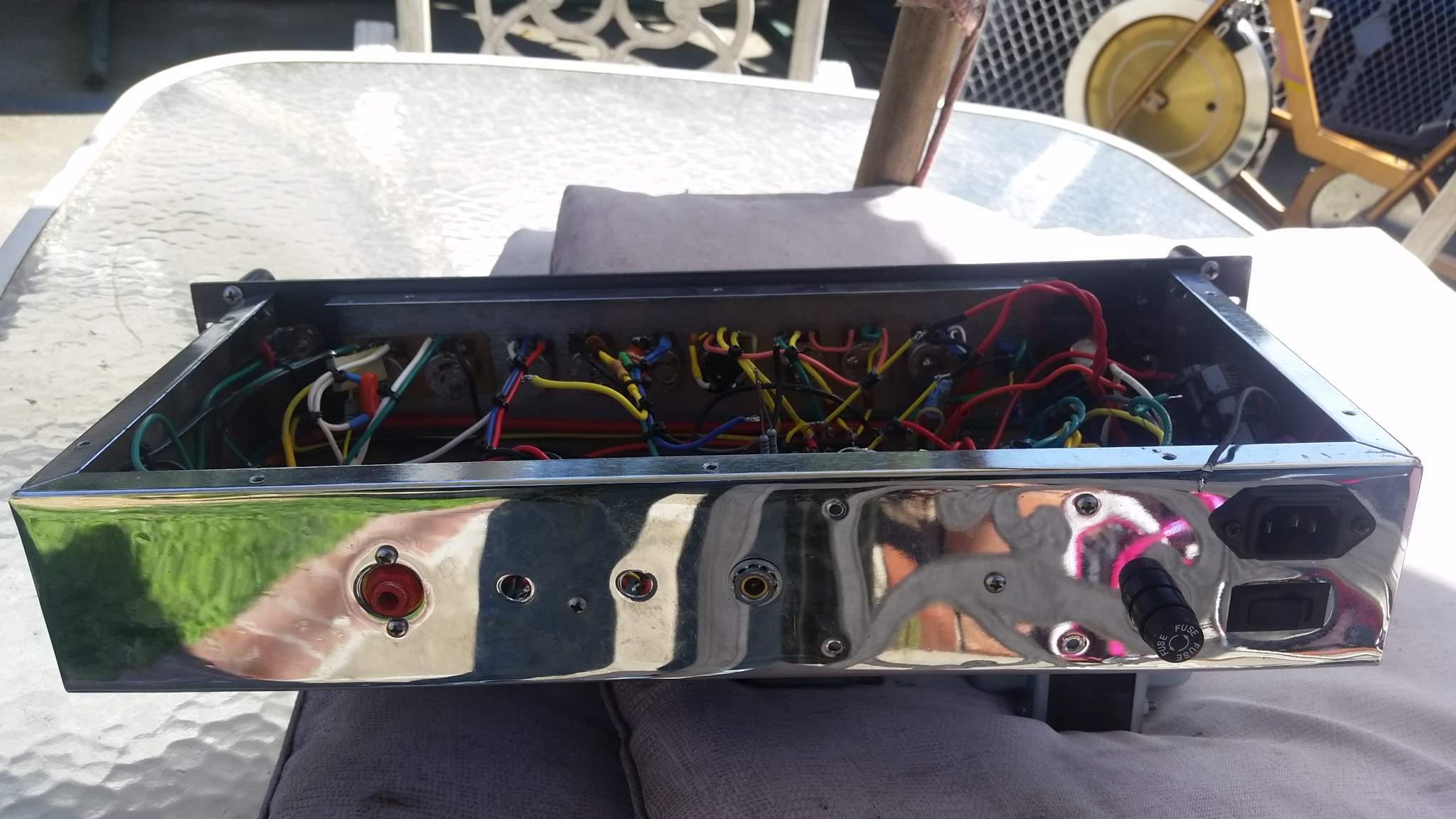
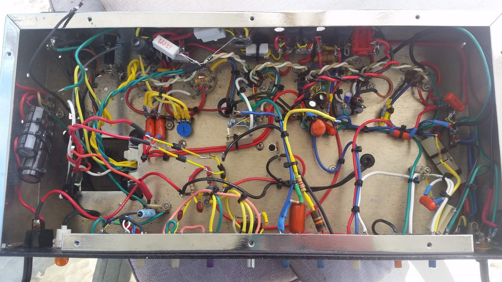
Ive dug out a chassis/carcass from a guitar amp build of mine from years ago.
Inspired by another thread on TB, I thought it might be fun to group build a simple tube bass preamp. That thread was full of ultra smarter than I cats, and didn't devolve into argument, and I hope that can happen here. I'd love to both learn some new tricks, and share what I know with everyone. I've never build one voiced for bass guitar before. I have enough major components for a build, I'll likely have to get only the small caps and resistors after we decide on values.
I have:
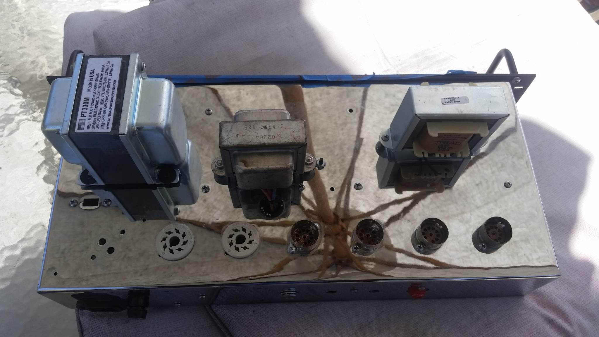
2 ru chassis with tube sockets
Power Transformer
Big power supply choke Choke
Diodes and caps for power supply, probably the higher wattage resistors also
Pots
Jacks
Some switches
Wire

Really, there's a whole amp, bUT we'really gonna start over and explain what everything does for everyone's benefit, maybe snag the interest of some non geeks who are curious.
I'll need help from the more knowledgeable on explaining things, and hopefully I get more educated along the way.

I have a fistful of 12ax7 on hand, and maybe a 12au7. So let's use those.
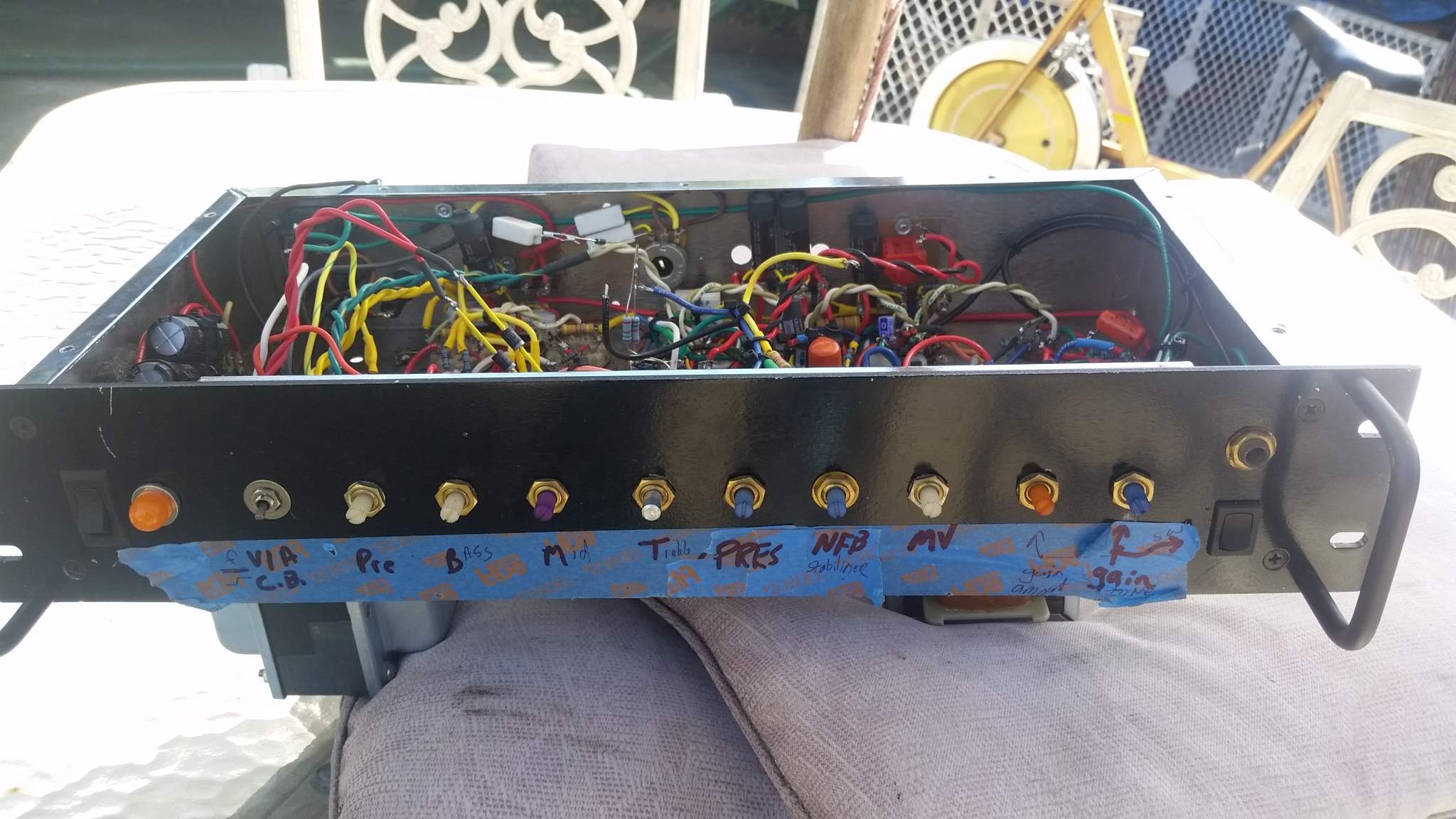
20160218_105343.jpg
20160218_105352.jpg
20160218_105406.jpg
20160218_105418.jpg
 
I don't want to make this a terribly complicated design. It'd be nice for it to be accessible for other TBers to build as well.
So the basic layout I've got in mind:
Four tubes. Active passive pad. 3 band eq (cathode driven). Master volume. Boost/gain circuit with single knob tone control
 
  • Like
Reactions: Barbaric.Eric
What kind of amp was/is the donor?
It's was an empty chassis. I bought a box of parts from Aspen Pittman awhile back for cheap, and that chassis was from him (Grove Tubes).
That amp was one of the guitar amps I built. Kinda of a bassman in the front end with a deluxe in the back. I've found a bunch of my hand drawn schematics from those builds. I can't find any with the phase inverter, but it won't matter here with this.
 
So 330vct for secondary b+ (330-0-330) 140mA
55vac for bias
2 heater taps, 6.3vac at 3.5a
And the other heater tap can be either 6.3 or 5 volt, 2a


Choke is 6h, 200mA.

Let's talk about power supplies then, good place to start. There are probably only 3 voltage we will need for a tube preamp:
The heaters.
B+ (plate)
And the 120v from the wall.

We won't need a bias supply since there is no output section (power tubes). We won't need 5v supply because I'm planning to use diodes instead of a tube rectifier.

I'll pause there to let someone chime in before we get further into the power supply.
 
Just a thought…

That power transformer should have enough juice to power a pair of 6V6s or EL84s in addition to a preamp. If you wanted to, you could do a take on the SWR IOD.

Also, since it has a 5V tap, you could make it tube rectified.
I don't know what a SWR IOD is, please do tell.
Yes, I bought the tranny to put in a 6v6 guitar amp build, and the sockets are in the chassis and I have an unused quartet).
I would like to come up with something real easy for other TB members to duplicate, and a diode rectifier is cheap and fast and easy. Plus, I have a magazine of diodes but not tube rect. on hand.
Let's talk abut that, what would be any advantages of going tube rectifier in this build? Keep in mind we have to do this like a teaching thing for folks just starting out. Myself, I think PSU sag isn't high on my personal list of bass preamp qualities. What are other advantages? I'd like to keep it to diodes and capacitors for ease/quickness, cheapness, aND maybe to not go buy a tube I don't have on hand.
 
1455832701030-1637842546.jpg

Unless we do use a tube rectifier, this is what one needs to know about a power transformer:
We've got the hot and neutral leads from the 120v power source (wall outlet) going into the primary side of the transformer. There are multiple secondary windings (sometimes referred to as taps) on the secondary side. These can be higher or lower voltages than the primary. In this case we have 6.3volts AC and 330volts AC on the 2 taps we's using. For sure we are going to turn the 330volts into DC power for the PLATES (anodes) of the tubes. We may leave the 6.3v as AC, or we may make it DC. I'm open to going either way on this. AC is simpler, albeit prone to being noisier. DC takes a few more steps, but is generally considered quieter.
I'd love some folks to chime in on this.
 
The SWR IOD was a preamp that had a pair of EL84 tubes running in AB with an OT as well. It could be used as a standard preamp or a small amplifier.
Once we get the preamp built and explained, there is no reason we couldn't carry on and build a phase inverter and output section. I'd love to talk about PI theory when we get there.

What do you think of the SS vs Tube rectifier question?
What do you think of the heater question (AC or dc)?
 
Once we get the preamp built and explained, there is no reason we couldn't carry on and build a phase inverter and output section. I'd love to talk about PI theory when we get there.

What do you think of the SS vs Tube rectifier question?
What do you think of the heater question (AC or dc)?
I'd say go SS rectifier. At least for now.

As for heaters, DC for the initial gain stage and AC for the others should provide a nice combination of easiness and sound quality.


I think.
 
  • Like
Reactions: rufus.K
14558332997331911164549.jpg
Here is what's in the chassis now as far as power supply goes for B+. I will break it down for those watching, unless we do something different. The numbers in parenthesis are actual values, and the ones not in them are design values.
I'm not opposed to trying something different. It's a very simple cap and resistor network. I think the PT is more than needed, so I may throw in the 6h choke just to tame it down, I'd love to hear what y'all experienced cats say on that too.
 
The SWR IOD uses a a small power section to simulate the feel of power tubes.

I say we use regulated supplies for both heaters and B+. Although, with that much choke we should definitely be able to get rid of AC ripple on the high power side (even without regulation). UF4007's (possibly bypassed) for the bridge rectifier with a CLCRC filter. Of course if we choose regulation, we could probably get away with just a CLC or even LC.
 
  • Like
Reactions: rufus.K