• TalkBass has been independent since 1998. Add your voice.
    Create a free account to reply to discussions, view embedded media, and browse with fewer display ads.
    Join freeLog in
    Want zero display ads or expanded classifieds tools? Compare plans.

Machine Shop Practice: Making Custom Metal Hardware For Basses

Holding parts accurately in drill press vises for, you know, drilling holes accurately in bass parts:

Coming up later in this thread, I'll go over the two main ways to locate holes when drilling. I call them Spot Drilling and Machine Drilling. Basically, Spot Drilling uses a center punch and "spot" in the part to guide the drill to its desired location. Machine Drilling locks the vise down in an accurate position in relation to the machine spindle. The drill then goes straight down into the part, with no guidance from a spot. Two different drilling techniques, each with their own rules and tricks. Don't mix them up!

With either technique, most metal parts should be held in a Drill Press Vise when drilling them in a drill press. A drill press vise is lighter duty than a milling machine vise, smaller and lighter weight. It's mostly made to take loads straight downward, not sideways.

When metalworking with drill presses, it's handy to have (at least) two drill press vises. Both with smooth jaws. One has a vertical V-notch in one jaw, which can be used for clamping round parts vertically while drilling the end.

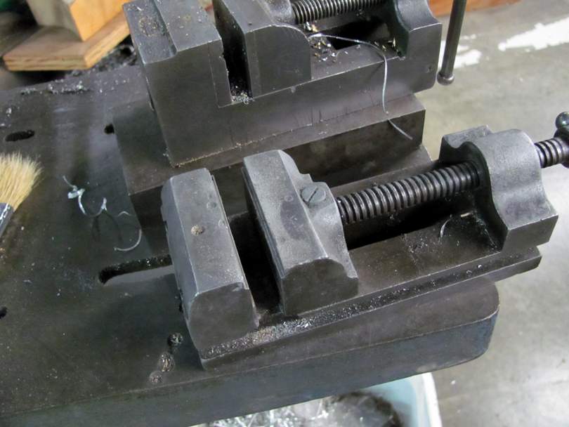
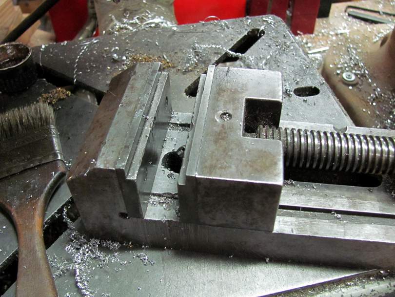
The other has milled steps in the tops of both jaws. These act as parallels, holding the part parallel to the table and perpendicular to the drill bit.
IMG_9442B.jpg


Like this. Those small rabbits in the jaws are important. Most parts are clamped in the vise sitting in those rabbits.
IMG_9441B.jpg


Here's a larger drill press vise which has wider and deeper rabbits. It can clamp the part with more force.

These are the vises I use for most Spot Drilling in drill presses. They need parallels (the rabbits) but they don't need stops. When Spot Drilling, the vise needs to be able to slide around on the drill press table. I'll explain why later.

When doing Machine Drilling in a drill press, the vise gets locked down in position on the drill press table. This is what those small X-Y vise units are made for.

IMG_8717B.jpg


These units combine a drill press vise with a small light-duty table with X and Y axis movements. It gets bolted down to the drill press table, and the X and Y axis movements allow you to adjust the position of the vise under the drill press spindle. These X-Y vise units aren't expensive, and they are very handy for drilling batches of parts.

These X-Y Vises are Not made for doing milling in your drill press! They aren't designed for it, nor is your drill press. Maybe some plastic parts for your model railroad. But not metal.
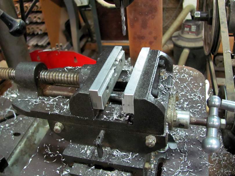
IMG_9451B.jpg


Look at the aluminum jaws that I've made up for mine. It's the old Rabbits and Stop thing. Note the little 4-40 socket head screw in the left jaw; that's the Stop.
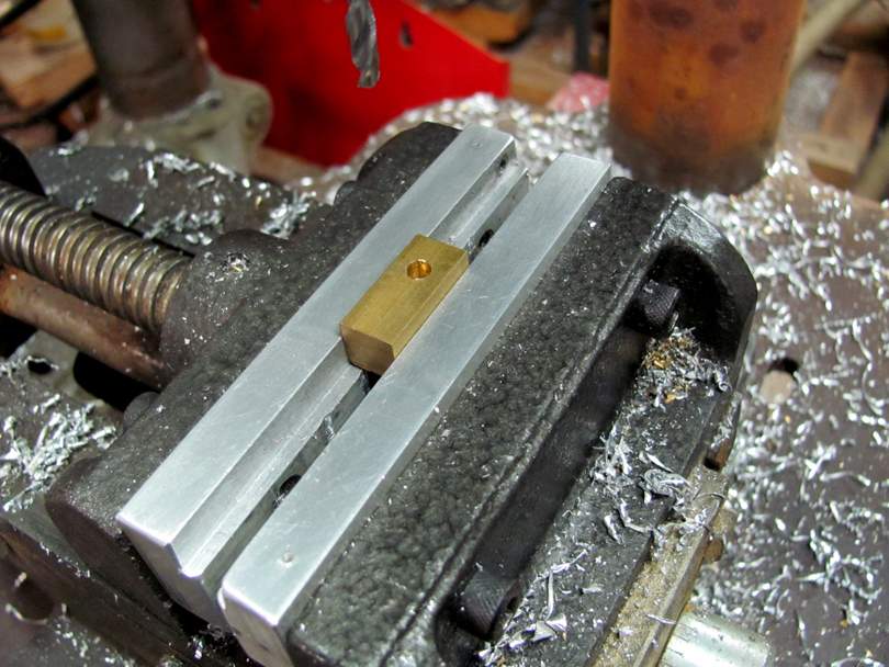
IMG_9452B.jpg


And here's how a typical part goes in there. It rests on the Rabbits and is pressing lightly against the Stop screw. The vise can be loosened and tightened with a half turn of the handle. I can change from one part to the next in several seconds, with the parts going to the same exact position each time. This is how you make batches of identical parts, using a drill press.

Coming up soon, I'll go over the process of Machine Drilling, and show the setup and operation.

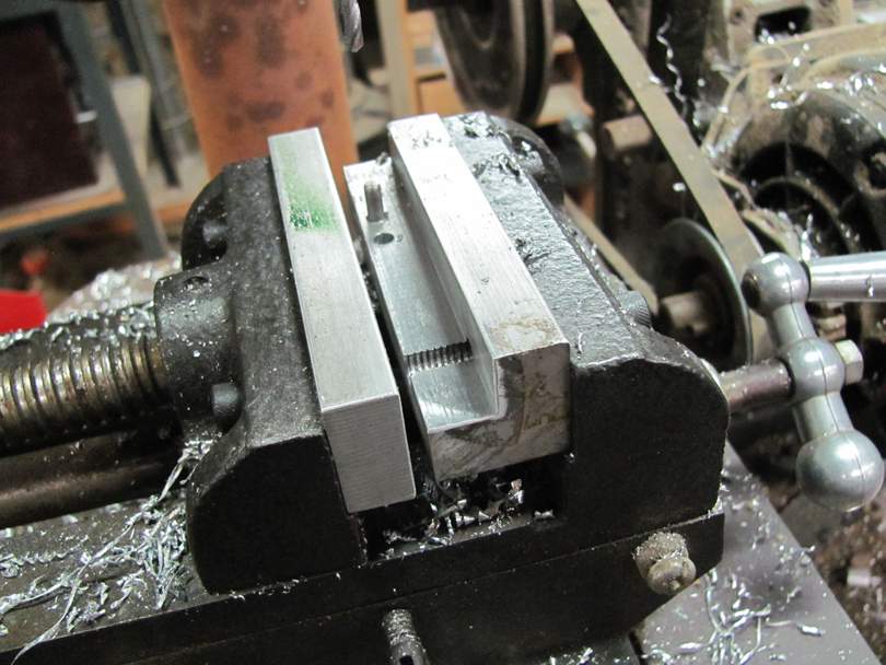
It's very easy to make up custom jaws for these vises. They normally come with smooth steel jaws, which are removable. They rest on a ledge in the vise casting and are held in with two 1/4"-20 screws. I make up all kinds of custom special-purpose jaws for my vises from aluminum bar stock. Not hard, and can be done without a milling machine.
IMG_9440B.jpg


Here's an example of a fancier set of custom jaws for my X-Y vise. The right jaw is milled with a 2 degree angle, and has a vertical pin. The left jaw is flat and smooth. I use these jaws and this drill press to drill a row of holes, all at a 2 degree angle, down the length of a piece of 5/8" round 6061 bar stock. These become a batch of truss rod anchors. I'll show the whole process when we get into making truss rods.

These jaws get taken off the vise, cleaned up, and put away in a special drawer. Special tooling, for making a specific part that I make by the hundreds. I invest a half hour making up these special jaws, and they will save me many hours over the years.
 
That post sent me looking at my drill vise (looks mostly like this one)
upload_2023-5-27_21-1-32.png


Unfortunately it doesn't have stepped jaws (something I really could use and didn't know existed.) I was please to see there are replacement jaws available for vises, but unfortunately I haven't found any stepped ones ... yet. My vice jaws are 4" wide, mounting holes are 2 3/8" apart.
 
That post sent me looking at my drill vise (looks mostly like this one)
View attachment 5075809

Unfortunately it doesn't have stepped jaws (something I really could use and didn't know existed.) I was please to see there are replacement jaws available for vises, but unfortunately I haven't found any stepped ones ... yet. My vice jaws are 4" wide, mounting holes are 2 3/8" apart.
I use a similar vise to yours, and I simply keep some extra hardwood planed a bit lower than the jaw height. When I need to use the vise in "stepped jaw" mode I simply cut a block an 1/8" narrower than the width of what I'm working on. Works fine, lasts a long time.
 
I use a similar vise to yours, and I simply keep some extra hardwood planed a bit lower than the jaw height. When I need to use the vise in "stepped jaw" mode I simply cut a block an 1/8" narrower than the width of what I'm working on. Works fine, lasts a long time.

Hey Rudy;

Sure wood works as parallels too!

In some cases, I make special parallel/holder blocks from MDF. For example:

IMG_2340B.jpg


In this operation, I'm milling a flat angled surface on the top of an aluminum Scroll Bass bridge. The milled surface is a facet, which then gets filed into a rounded top surface. Decorative, no need for super accuracy. The MDF block just holds the bridge at a consistent angle and height in the vise. A block like this takes minutes to make. Layout in pencil, bandsaw. It doesn't have to be any fancier than that. The MDF block gets marked with a Sharpie and put away in the box of Bridge Tooling. Ready for use whenever I make up the next batch of bridges.

Edit:

Note that there are three of those custom MDF holding blocks stored away neatly in the Scroll Bass Bridge Tooling box. Ready for the next time I need to make up a batch of bridges. Simple, quick tooling that saves so much time.

IMG_9448B.jpg
 
Last edited:
That post sent me looking at my drill vise (looks mostly like this one)
View attachment 5075809

Unfortunately it doesn't have stepped jaws (something I really could use and didn't know existed.) I was please to see there are replacement jaws available for vises, but unfortunately I haven't found any stepped ones ... yet. My vice jaws are 4" wide, mounting holes are 2 3/8" apart.

Hey RW;

That's the style of most modern drill press vises that come with the imported drill presses. They are available for cheap, and they work okay. Low profile and wide. They aren't a strong as the old-style ones that I prefer, but they do the job.

The jaws on those vises are simple steel plates, held on by two screws each. It's easy to make up some replacement stepped jaws for it from aluminum or steel. You can make them without a milling machine, using two pieces that are offset in height.

I just noticed that I have one of those vises here, sitting on a shelf, covered with dust. I found it in one of the estates that I cleared out, and kept it because I thought it could be useful. It's one of the larger 5" wide sizes. Most of them that you see are the 4" size.

IMG_9481B.jpg


IMG_9482B.jpg


Here it is, dusted off. It's in good shape, nothing wrong with it. Hmmm... I should just make up a set of aluminum stepped jaws for it right now. Using just a drill press, no milling machine. As a demonstration of how to do this. I'm guessing that most of you who have non-antique drill presses, have one of these vises, right? A quick little metalworking project to help you with future metalworking projects.
 
Holding parts accurately in drill press vises for, you know, drilling holes accurately in bass parts...

Thanks for this whole thread Bruce, very helpful as always.

Your drill press post in particular was a bit of deja vu as I had a day off on Friday and spent part of it building a pull block for a headless tuner using my drill press. One of the issues I had to deal with was holding the workpiece flat in the jaws as my vise has no steps in the jaws. Since reading your post I will make something to solve this: either new jaws or maybe just a hardwood parallel.

Before I go further, let me make 2 things clear:
  1. I have never done this complexity of metalwork on a drill press before
  2. I have about the cheapest setup possible: a benchtop import drill press with an import cross slide vise
If I can do this sort of thing then anyone can! :thumbsup:

I started off with a FreeCAD drawing:
bridge_pull_block_cad.jpg

Since FreeCAD is free anyone can do drawings like this also.

Then sliced off a just over 1" slug from a 1/2" square brass bar with a hacksaw. Then measured and marked the holes on each face with a punch and deepened them with a carbide spotting bit.

Next I drilled a 2.6 mm hole in the end so it could be tapped with M3 x 0.35 mm (metric fine, equivalent to 73 TPI) threads. Theoretically the threads should be more than strong enough for the ~50 lbf string tension required but... more on that in this post:

bridge_thread_hole.jpg


Then tapped using the drill chuck to keep the tap perpendicular to the hole. I clamped a weight onto one of the handles to keep a small amount of downward force on the tap while turning the chuck by hand. Note: do not use the drill motor to drive the tap as it is important to back off the tap every half a turn or so to clear chips. I used some aluminum cutting fluid, which also works well for soft metals, for both drilling and tapping:

bridge_tap.jpg


Then onto the top and side holes. These were done with standard HSS twist bits but with the cutting edge of the bits flattened with some sandpaper to keep the brass from grabbing the bit and pulling it into the workpiece too quickly. I used a step bit to put a chamfer on the holes which works better than just using a drill bit as the step bit is self-centering which helps avoid chatter.

I then needed to put a slot in the end of the block for the string to pass through. This was done with a 1/8" carbide spiral flute end mill and, as Bruce points out, drill presses aren't good metal mills. If the end mill had been any larger it wouldn't have ended as well as it did. Even this small end mill is tough to control well on a vise with as much slop in the "Y" axis (the top slide which moves front to back) as these cheap import vises have. I ended up making the slot slightly wider than planned to get the surface finish better, but it still isn't great:
bridge_block_mill.jpg


That was followed by a quick touch of each face to the belt sander to cleanup the surface corrosion and give it a brushed look, and it was done:
bridge_block_finished.jpg
 
Last edited:
Thanks for this whole thread Bruce, very helpful as always.

Your drill press post in particular was a bit of de ja-vu as I had a day off on Friday and spent part of it building a pull block for a headless tuner using my drill press. One of the issues I had to deal with was holding the workpiece flat in the jaws as my vice has no steps in the jaws. Since reading your post I will make something to solve this: either new jaws or maybe just a hardwood parallel.

Before I go further, let me make 2 things clear:
  1. I have never done this complexity of metalwork on a drill press before
  2. I have about the cheapest setup possible: a benchtop import drill press with an import cross slide vice
If I can do this sort of thing then anyone can! :thumbsup:

I started off with a FreeCAD drawing:
View attachment 5076986
Since FreeCAD is free anyone can do drawings like this also.

Then sliced off a just over 1" slug from a 1/2" square brass bar with a hacksaw. Then measured and marked the holes on each face with a punch and deepened them with a carbide spotting bit.

Next I drilled a 2.6 mm hole in the end so it could be tapped with M3 x 0.35 mm (metric fine, equivalent to 73 TPI) threads. Theoretically the threads should be more than strong enough for the ~50 lbf string tension required but... more on that in this post:

View attachment 5077051

Then tapped using the drill chuck to keep the tap perpendicular to the hole. I clamped a weight onto one of the handles to keep a small amount of downward force on the tap while turning the chuck by hand. Note: do not use the drill motor to drive the tap as it is important to back off the tap every half a turn or so to clear chips. I used some aluminum cutting fluid, which also works well for soft metals, for both drilling and tapping:

View attachment 5077060

Then onto the top and side holes. These were done with standard HSS twist bits but with the cutting edge of the bits flattened with some sandpaper to keep the brass from grabbing the bit and pulling it into the workpiece too quickly. I used a step bit to put a chamfer on the holes which works better than just using a drill bit as the step bit is self-centering which helps avoid chatter.

I then needed to put a slot in the end of the block for the string to pass through. This was done with a 1/8" carbide spiral flute end mill and, as Bruce points out, drill presses aren't good metal mills. If the end mill had been any larger it wouldn't have ended as well as it did. Even this small end mill is tough to control well on a vice with as much slop in the "Y" axis (the top slide which moves front to back) as these cheap import vices have. I ended up making the slot slightly wider than planned to get the surface finish better, but it still isn't great:
View attachment 5077075

That was followed by a quick touch of each face to the belt sander to cleanup the surface corrosion and give it a brushed look, and it was done:
View attachment 5077067

Looks great and a project very close to my own ambitions. Will these be loaded onto recessed tuners or will it be sufficiently low-profile to mount at surface height?
 
  • Like
Reactions: Jeff Siddall
That post sent me looking at my drill vise (looks mostly like this one)
View attachment 5075809

Unfortunately it doesn't have stepped jaws (something I really could use and didn't know existed.) I was please to see there are replacement jaws available for vises, but unfortunately I haven't found any stepped ones ... yet. My vice jaws are 4" wide, mounting holes are 2 3/8" apart.
I’d highly recommend you make a set of soft jaws for your vise from some sheet aluminum or copper etc. They can be a slip fit over the existing jaws.
 
Last night I went ahead and made up a quick set of stepped aluminum jaws for that imported drill press vise that I showed above. To demonstrate the process to all of you. And I made them using just a drill press. No big heavy expensive machines. Well okay, several drill presses, because I have them and they were all set up and ready to go. And I did use my powered Small cutoff bandsaw, rather than a hacksaw.


IMG_9482B.jpg


Here's the vise, one of the typical import low-cost, low-profile drill press vises that are available everywhere drill presses are sold. Not real strong or well made, but they work okay. And they are cheap. A set of aluminum stepped jaws will make it more useful.

IMG_9483B.jpg


And here's the trick to making the rabbited jaws without a milling machine: Make the jaws in two pieces from two sizes of aluminum bar stock. The upper bar is 1/4" x 1" and the lower is 1/4" x 3/4". You can pick the sizes of the bar stock to make the rabbited step whatever size you like. In this case, the step will end up 1/4" x 1/4".

IMG_9484B.jpg


Stick the bar stock in the vise and mark off the length, to whatever length you want. You can let the jaws extend out the sides if you like.

IMG_9485B.jpg


I sawed the two bars off to length in my cutoff bandsaw. I could have done it quickly with a hacksaw in a vise, but I have the bandsaw right there. I also quickly smoothed and deburred the ends of the bars on the Knife Belt Sander and the finishing wheel. I could have used files.....

And there's the other helpful trick: Roll Pins. If you aren't familiar with roll pins, they are steel pins which are made from spring steel rolled into a hollow C-shape. When you tap them into a hole, like a nail, they compress in diameter a little bit, and exert a lot of force to the hole. A cheap fast way to fasten two metal parts together. I use them a lot in building tooling and machine parts. These are 1/8" x 1/2" roll pins.

IMG_9486B.jpg


I'm going to use the roll pins to lock the pairs of bar stock together; one pin out at each end. I did a quick layout, just on the narrower bars, of where to locate the holes. Small square, scribed lines, center punch, spot drill.......I'll go into that technique in more detail when we get into Spot Drilling.

IMG_9487B.jpg


Another Secret Trick: I clamp the 1" wide bar in the vise, with the 3/4" bar resting on top of it. I push the 3/4" bar against the near-side jaw, and lightly clamp it in place with a small pair of Vise-Grips. This lines up the bottom edges of both bars. Held like that, I drill an 1/8" hole down through both bars. Just the one end.

IMG_9488B.jpg


Still holding them with the Vise Grips, I take them out of the vise and gently set them on my handy nearby anvil. I tap in a roll pin, just like a little nail. Flush to the surface.

IMG_9489B.jpg


With the Vise-Grips off, it goes back in the vise to drill the pin hole in the other end. While drilling, I keep a finger on the end of the 3/4" bar, to make sure it stays seated against the vise jaw.

IMG_9490B.jpg


Tapped in the pins. Cleaned up the ends on the Finishing Wheel. And there's the two jaws, blanked out and ready to be fitted into the vise.
 
Fitting the new aluminum jaws into the import drill press vise:

IMG_9491B.jpg


Here are the original jaws from the vise. They are held in by two 6mm countersunk screws each. I'm going to use the same screws to mount the new jaws.

Take a look at those steel jaws. Notice how the bars aren't equal width end-to-end. And the screw hole locations aren't equal distance from the edges. The engineering term for this is Catty-Wompus. Very low manufacturing standards. The threaded holes in the vise castings are not in precise positions. So the steel jaws were ground on top (by hand, I'm sure) to be flush. And look precision.

IMG_9492B.jpg


This Catty-Wompus behavior calls for Match Drilling. That is, I use the actual original steel jaws to mark the locations of the mounting holes in the new jaws. Being careful to get the correct side down. And also noting that the hole positions in the two jaws will be slightly different from each other. Each jaw will fit one side.

I mark the hole locations with the automatic centerpunch. I could have gotten fancy and used a Transfer Punch, but this is good enough.

IMG_9493B.jpg


After spotting the holes, I drill them 1/8" straight through. These are pilot holes.

IMG_9494B.jpg


Then I drill 13/32" down through, almost to the bottom. That's the size bit that clears the heads of the 6mm screws, and leaves a countersink down at the bottom. I did this drilling in my big Royersford drill press, just because it's more fun.

IMG_9495B.jpg


Then I drilled 1/4" down through, for clearance for the screws.

IMG_9496B.jpg


A light countersink on the mounting holes, front and back, and the jaws are ready to install!

IMG_9497B.jpg


And there they are, screwed in place. Because of the Catty-Wompusness, I had them in the wrong places the first time. They fit better when I reversed them.

IMG_9498B.jpg


There was a slight misalignment of the steps at one end....so, I clamped a piece of scrap aluminum between the jaws and.....

IMG_9499B.jpg


...Took a few strokes of my big square file down the steps to true them up to each other. Now they are good.

IMG_9500B.jpg


And there's the vise, with its cool new jaws, ready for service. I'm glad I pulled it off the shelf and fixed it up. It will be useful here in my metal shop. It's lower profile and wider than my other small vises.

These stepped jaws, made like this, are probably within 0.005" of parallel to the bottom surface of the vise. Good enough for most drilling jobs. If I wanted to make them more accurate than that, I could spend a little more time with a file and calipers. Or, pop the whole vise in the milling machine and make a trim pass down the steps with an End Mill.
 
Last edited:
Looks great and a project very close to my own ambitions. Will these be loaded onto recessed tuners or will it be sufficiently low-profile to mount at surface height?

Yes, loaded into an aluminum/wood bridge which will be recessed and angled down at perhaps 10 degrees to provide suitable break angle across the saddles. For more info on that project look here.
 
What a cool thread! Gonna hafta read the whole thing. Another great Bruce Johnson masterclass & roundtable.

I'm hopeful that people will add onto this from the standpoint of using what I'd call "normal" tools. I know there's some of you making some amazing stuff without a metal lathe, or a mill. Guys using just the typical drill press, some files and so on. I think there's tons of value in sharing that since the majority of us don't own the endless array of machines Mr. Bruce does. I say that from a sheer standpoint of jealousy Bruce. ;) :smug:
This tailpiece was definitely a "normal tool" hack-job by a non metalworker. Minimalist as heck.
I had a drill press, hack saw, and a Dremel.
That's about it.
It came out ok. :meh:
Screenshot_20230529_134017_Chrome.jpg
Screenshot_20230529_134036_Chrome.jpg
Screenshot_20230529_134059_Chrome.jpg
 
One note about "Catty-Wompusness".
After making a few jigs out of metal, measuring everything so the layout was equal distances for mounting bolts and the like I realized that I was always getting jig or fixture parts aligned incorrectly, and the small discrepancies in where mounting holes were positioned always made it difficult to figure out which way was correct without marking their locations. I quickly figured out that purposefully introducing obvious "catty-wompusness" made it MUCH easier to get parts lined up correctly. If mounting holes are 1/2" different on left and right sides of parts then it's instantly apparent which way everything fits together.
If this seems hard to understand it will become clear to you if you make a few things that bolt together. The vise jaws worked over by Bruce are a good example. If the mounting holes are 1/4" different left to right then it will be easy pie to know which jaw goes where.

My father-in-law was a tool and gauge maker at a large manufacturing plant and he greatly helped me understand how standard tools like sine bars, jowl blocks, 1-2-3 blocks, etc. functioned. He also told me as Bruce relayed that "2/10ths of a thousandth" was their normal working tolerance for gauge making. I'm glad musical instruments don't require that sort of precision! :)

It was always nice to visit the tool and gauge shop because it was temperature stable so the huge granite surface plates would be FLAT. Those blocks were something like 18" thick, so they weren't going anywhere.
 
Last edited:
One note about "Catty-Wompusness".
After making a few jigs out of metal, measuring everything so the layout was equal distances for mounting bolts and the like I realized that I was always getting jig or fixture parts aligned incorrectly, and the small discrepancies in where mounting holes were positioned always made it difficult to figure out which way was correct without marking their locations. I quickly figured out that purposefully introducing obvious "catty-wompusness" made it MUCH easier to get parts lined up correctly. If mounting holes are 1/2" different on left and right sides of parts then it's instantly apparent which way everything fits together.
If this seems hard to understand it will become clear to you if you make a few things that bolt together. The vise jaws worked over by Bruce are a good example. If the mounting holes are 1/4" different left to right then it will be easy pie to know which jaw goes where.

My father-in-law was a tool and gauge maker at a large manufacturing plant and he greatly helped me understand how standard tools like sine bars, jowl blocks, 1-2-3 blocks, etc. functioned. He also told me as Bruce relayed that "2/10ths of a thousandth" was their normal working tolerance for gauge making. I'm glad musical instruments don't require that sort of precision! :)

It was always nice to visit the tool and gauge shop because it was temperature stable so the huge granite surface plates would be FLAT. Those blocks were something like 18" thick, so they weren't going anywhere.

Yes, absolutely! When building machines, it's usually very important that they can be disassembled and reassembled fairly easily. And so, it's also very important that the parts get put back together the right way. There's a lot of different ways to assure that. Deliberately making bolt patterns a little bit non-symmetric (Catty-Wompus), Adding dowel pins at non-symmetric locations, making marks with punches and chisels, etc.

I often do the same tricks when making up routing fixtures from MDF, for woodworking. I put those fixtures together with screws so they can taken apart for fixes and modifications. And I use marks and pins so they can be put back together the same way.

I learned most of my machine shop skills (and welding/fabrication skills) way back in the late '70's when I worked for 5 years for a small company building components for race cars. We had an old worn-out LeBlond lathe and a Bridgeport mill. There was a kind older German gentleman named Dave who we hired to work part time for us machining parts. I was 19, and fascinated by the machines. He spent a lot of time with me and taught me so many of the basics. And then there was Tom Bowman, who had his own serious machine shop nearby. He was a real Tool & Die level machinist who did custom work for the DoD, and also liked to build hot rods and race cars. He would make the really difficult and high-precision parts for us. I used to hang around his shop, gawking at all his beautiful machines! I also learned a tremendous amount from him. Those years are when I locked into my love of....shops full of machines.

I paid my way through college doing all that race car work, got a Mechanical Engineering degree. I interviewed at a defense contractor, a medium size plant that built howitzers for the Army. They didn't have any openings for Mechanical Engineers at that moment, but they offered me a job as a Quality Engineer as a starting position. I thought about it, and I'm so glad I took it. I spent a year working in the inspection labs, and down on the factory floor, learning all about precision measurement techniques and making parts to tight specifications. That was a great foundation to my education as an Engineer. Then I moved into Mechanical Engineering, and then into the R & D engineering world. Where I worked for 25+ years. Then I became a Luthier...with my own very cool shop full of machines!
 
What a cool thread! Gonna hafta read the whole thing. Another great Bruce Johnson masterclass & roundtable.


This tailpiece was definitely a "normal tool" hack-job by a non metalworker. Minimalist as heck.
I had a drill press, hack saw, and a Dremel.
That's about it.
It came out ok. :meh:View attachment 5077977 View attachment 5077978 View attachment 5077979

Hello Kevin! I was hoping you'd join in the discussions here. You've done a lot of very nice non-metalworker metalworking. That tailpiece is a great example of a custom part that adds so much character and value to your bass. It looks hard to make, but it really isn't. It's all about sequence of operations and making use of the tools you have.
 
This is what I was working on last night, in case you were wondering:

IMG_9501B.jpg


Makin' aluminum chips with the big 'ol Kondia milling machine. Finishing up a batch of replacement aluminum bridges for vintage Ampeg AEB-1 and AMB-1 Scroll Basses. These bridges are almost the same as the bridges I make for my new Scroll Basses; just a few dimensional differences. Machined from 6061 bar stock. Drilled holes, milled surfaces and milled slots for the saddles to fit in.

Here I'm finishing up milling the saddle slots with a 3/8" end mill. I'm using a tricky setup of parallels, a stop, and a front clamping block in the vise to hold the bridges in accurate position. The Kondia has enough power and strength that I can cut these slots in a single pass, plowing in from the back edge and stopping at a Zero'd position. I have to lift the quill up at each end of the pass to add a few drops of cutting oil.


IMG_9503B.jpg


Here they are with the slots finished. It took me about 4.6 hours to mill 48 slots in 12 bridges. About 22 minutes per bridge, for this operation.