
Enjoy the benefits of a premium membership!
Upgrade Account
-
TalkBass has been independent since 1998. Add your voice.
Create a free account to reply to discussions, view embedded media, and browse with fewer display ads.
Join free Log in
Want zero display ads or expanded classifieds tools? Compare plans.
You are using an out of date browser. It may not display this or other websites correctly.
You should upgrade or use an alternative browser.
You should upgrade or use an alternative browser.
Magnets & Copper Wire: A Pickup Building Thread
- Thread starter Freekmagnet
- Start date
More options
Who Replied?


I don't know any suppliers in the EU or Asia but I will say I hope you do share your project in this thread! Sounds like an interesting and unique design.
For now I can only share really messy and crappy looking prototypes and design ideas. In part I do want to share and get some ideas, opinions an criticisms, and in part I'm "shy" since there are so many good looking real pickups posted here

I might try to get some courage and post


For now I can only share really messy and crappy looking prototypes and design ideas. In part I do want to share and get some ideas, opinions an criticisms, and in part I'm "shy" since there are so many good looking real pickups posted here
I might try to get some courage and post
Dude, I started this thread, and I’ve posted some really crappy prototypes here myself. I say post away! Haha Its not fair to just toy with our emotions like this!
Last edited:

So far I have used neodymium cylinders and rings and both sound kinda good (especially with a filter based preamp). The bobbins have 5000 turns of 0.06mm (AWG 42 or 43 maybe?) wire and for now they need a preamp with 2× gain for the same level as my passive bass. That's one other thing I'd like to improve, but then again is there anything stronger than neodymium and will it make a difference.
5000 turns of 42 AWG seems low and may cause a low output. You can check the DC resistance and compare it to pickups that you like. 42 AWG has about 1668.8 Ohms per 1000 feet.
Posting pictures is helpful and interesting for everyone reading this thread.
Ok since you guys asked for it, I'm gonna share what I've done with my project so far..
Introduction:
I've always been obsessed with reverse engineering and building things that I can't afford. Some time ago I got the idea that I wanted to get a sound like Justin Chancellor (Wal bass, band: Tool), and therefore set on an "epic" quest to build something that will get me close to that. Electronics is my profession, so that part was okish, but I suck big time in mechanical engineering, or building anything that needs at least some "mechanical" skills. Skipping some 10 years to the present, I picked up this project again and this is what I have so far.
Cover no.1:
My original idea was to make a wooden cover. If done right, it would look cool, and be easier to align the bobbins right under the strings. Also it being a soapbar pickup, I thought it sould be pretty easy to cot out a block of wood. I was wrong of course, and abandoned the idea for now. Also it was a pain to work with wood considering all the bobbin and magnet changing and stuff. Here is a prototype cover made from a random branch of walnut from a local forest.


Bobbins:
For the bobbins I used a threaded insert for the centre pillar and ordered circular PCB's for the plates at the end. The thread would ensure that the pole piece, which is a M4 screw is held in place and can be height adjusted if needed (inspired by pictures of Wal pickups of course). The PCBs have pads on them so I can solder the pickup wire directly to them. The pads are also large enough so I can solder lead wire to them. It's glued together with epoxy.

Due to the crappy glue job resulting in an uneven centre pillar and the wobble in the winding machine, they didn't end up "perfect" the first time.
I tried a version where I threaded some plastic spacers and glued with CA glue. The end results were prettier. But the bobbins had structural issues, as apparently CA glue doesn't stick so good to PCB's as epoxy does.

All in all, I managed to fit 5000 turns of AWG43 wire. Each coil has a DC resistance of 850Ohm. I measured the resonant frequency of the coils and it's around 80kHz (I should repeat that with better settings to get a super accurate measurement). I still have no clue what would be the total resonant frequency when I connect them in the pickup.
Cover no2. and magnets:
In the mean time I decided to equip my PJ bass wit multi coils as well. Since making P and J pickups out of wood is impossible for me, I turned to to 3D printing. I made Covers for the P and J as well as for the EM40s for my original bass.
I also opted to ditch the headless screws and get cheese head screws so I get a wider sensing area under the string. I have no idea if that's going to make any difference, ut it looked cooler to me
For the PJ I installed ring magnets. The only ones I could get off ebay were the ones wit a screw hole, which is something I'm not happy about - I'd like real rings. The problem is that they fly all over the place, so I needed to fasten them with a nut. At least until I glue them, and fill in the cover with epoxy.
For the EMG40, I 3D printed a plate that holds small cylinder magnets and just fits in the main cover. The magnets don't have physical contact with the pole pieces, but it shouldn't be a problem, I mean they do work ;D


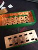


End results:
They all work. I tried to do use filler spray on the plastic to get it smooth and do a paint job, but that came out reeeeeealy bad and I don't have photos of that.
I tried various combinations with the wiring, but it was a real pain with the current magnet configuration, so I just settled with all series for the PJ (wired in humbucking mode), and one humbucker per string for the EMG40, then all summed in an active buffer.
What next?:
I'm going to try getting PA12 Nylon bobbins made in China and try to get more windings in there.
I'd like to find some "normal" sized bar magnets, so I can make steel keepers for the pole pieces like every other normal human being does. This seems overly complicated so far.
Id like to revisit my idea of wooden covers, but I'll need better magnet solutions for that.
Also, any other good ideas would be appreciated.
Introduction:
I've always been obsessed with reverse engineering and building things that I can't afford. Some time ago I got the idea that I wanted to get a sound like Justin Chancellor (Wal bass, band: Tool), and therefore set on an "epic" quest to build something that will get me close to that. Electronics is my profession, so that part was okish, but I suck big time in mechanical engineering, or building anything that needs at least some "mechanical" skills. Skipping some 10 years to the present, I picked up this project again and this is what I have so far.
Cover no.1:
My original idea was to make a wooden cover. If done right, it would look cool, and be easier to align the bobbins right under the strings. Also it being a soapbar pickup, I thought it sould be pretty easy to cot out a block of wood. I was wrong of course, and abandoned the idea for now. Also it was a pain to work with wood considering all the bobbin and magnet changing and stuff. Here is a prototype cover made from a random branch of walnut from a local forest.
Bobbins:
For the bobbins I used a threaded insert for the centre pillar and ordered circular PCB's for the plates at the end. The thread would ensure that the pole piece, which is a M4 screw is held in place and can be height adjusted if needed (inspired by pictures of Wal pickups of course). The PCBs have pads on them so I can solder the pickup wire directly to them. The pads are also large enough so I can solder lead wire to them. It's glued together with epoxy.
Due to the crappy glue job resulting in an uneven centre pillar and the wobble in the winding machine, they didn't end up "perfect" the first time.
I tried a version where I threaded some plastic spacers and glued with CA glue. The end results were prettier. But the bobbins had structural issues, as apparently CA glue doesn't stick so good to PCB's as epoxy does.
All in all, I managed to fit 5000 turns of AWG43 wire. Each coil has a DC resistance of 850Ohm. I measured the resonant frequency of the coils and it's around 80kHz (I should repeat that with better settings to get a super accurate measurement). I still have no clue what would be the total resonant frequency when I connect them in the pickup.
Cover no2. and magnets:
In the mean time I decided to equip my PJ bass wit multi coils as well. Since making P and J pickups out of wood is impossible for me, I turned to to 3D printing. I made Covers for the P and J as well as for the EM40s for my original bass.
I also opted to ditch the headless screws and get cheese head screws so I get a wider sensing area under the string. I have no idea if that's going to make any difference, ut it looked cooler to me
For the PJ I installed ring magnets. The only ones I could get off ebay were the ones wit a screw hole, which is something I'm not happy about - I'd like real rings. The problem is that they fly all over the place, so I needed to fasten them with a nut. At least until I glue them, and fill in the cover with epoxy.
For the EMG40, I 3D printed a plate that holds small cylinder magnets and just fits in the main cover. The magnets don't have physical contact with the pole pieces, but it shouldn't be a problem, I mean they do work ;D
End results:
They all work. I tried to do use filler spray on the plastic to get it smooth and do a paint job, but that came out reeeeeealy bad and I don't have photos of that.
I tried various combinations with the wiring, but it was a real pain with the current magnet configuration, so I just settled with all series for the PJ (wired in humbucking mode), and one humbucker per string for the EMG40, then all summed in an active buffer.
What next?:
I'm going to try getting PA12 Nylon bobbins made in China and try to get more windings in there.
I'd like to find some "normal" sized bar magnets, so I can make steel keepers for the pole pieces like every other normal human being does. This seems overly complicated so far.
Id like to revisit my idea of wooden covers, but I'll need better magnet solutions for that.
Also, any other good ideas would be appreciated.
5000 turns of 42 AWG seems low and may cause a low output. You can check the DC resistance and compare it to pickups that you like. 42 AWG has about 1668.8 Ohms per 1000 feet.
Posting pictures is helpful and interesting for everyone reading this thread.
Yeah, it does sound a bit too low. But I did think of a way how to compare pickups without taking into consideration the effects of the magnet.
I used one of my coils a to generate a magnetic filed which would excite the measured coil. I just connected it to a signal generator, got a very high output voltage (10~20Vpp) and put it above the pickup I want to excite, so that the magnetic filed of that coil goes directly through the pickup windings (in line with the pole pieces).
Then I connected the measured pickups to a oscilloscope and measured the voltage.
This of course isn't an exact measurement, but you can get comparative results to a "known" pickup.
I compared my bobbins to the stock pickups of my basses.
So with the same source applied to the Jazz pickup gave an output of ~2.5Vpp, on the precision pickup ~2.45V, and each coil of the EMG40 has ~750mVpp.
Compared to that my coils gave only ~480mVpp.
Which in total would mean about 1.5× to 2.5× less signal then the stock ones.
Now as I said, this doesn't take into consideration the strength of the magnet, so I can't really predict the total output signal if the pickups used different magnets.
Also, I still haven't figured out how much windings I would need to add to get the same output. I'm to lazy to do the math at the moment

I recently upgraded my process for casting bobbins for my pickups.
First, I made up a new Master from which to make the molds. I drew it up in Cad, and machined it from aluminum as I had before.
The Master starts out as a block of 1 1/2" x 1 1/2" square 6061 aluminum bar stock. Clamped in the vise of the mill, drilled the holes, milled away the sides....
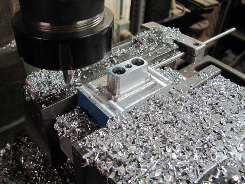
Here it is roughly milled....
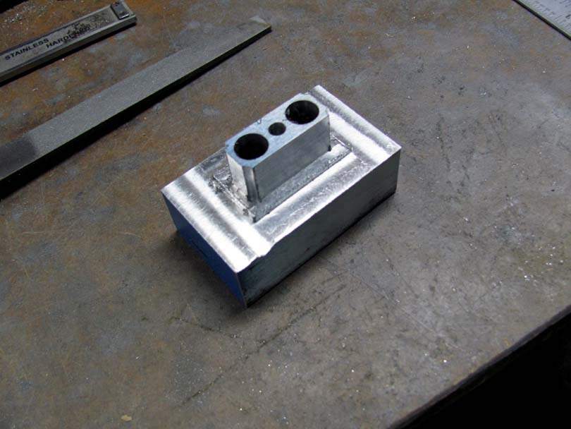
Hand filing the radiuses on the ends and around the flange.....
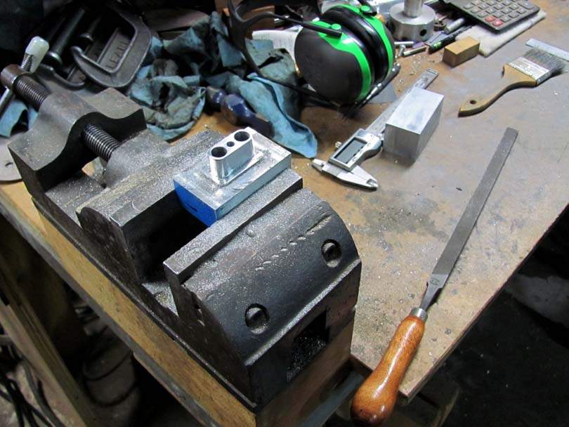
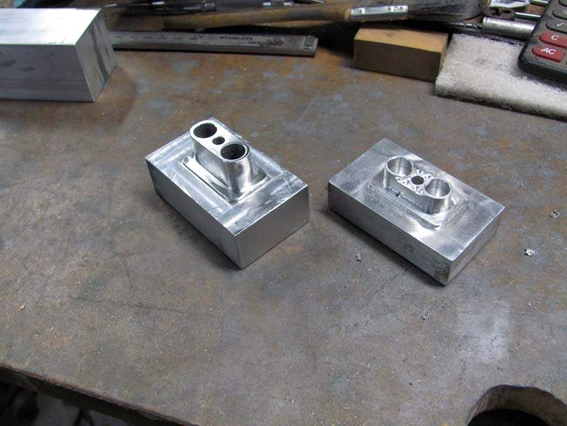
A light polishing, and it's ready. This is an extended height bobbin half, for a new model of my pickup that uses 3/8" x 1" magnets. The other Master on the right is for the standard height lower half. I made it around 2010. Now, I upgraded it by precisely drilling the holes for the magnets and center pin. I'll show you why below.
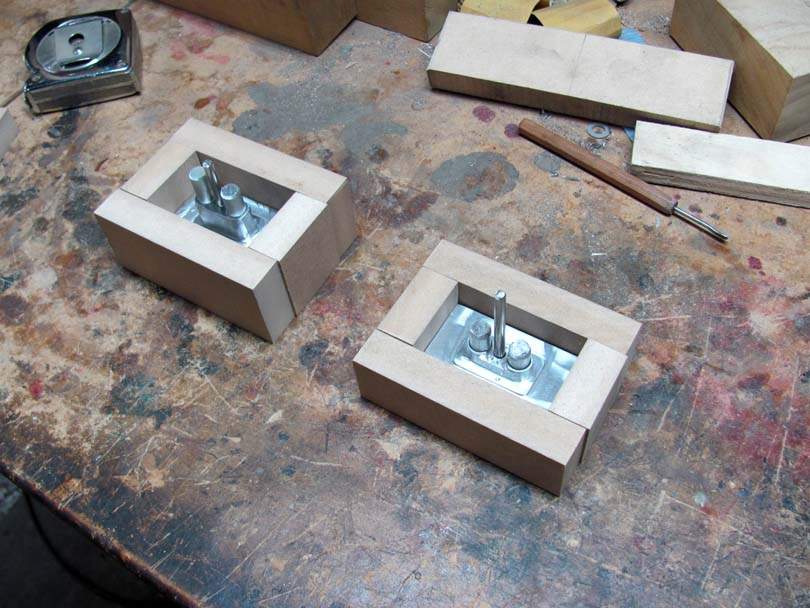
Preparing to cast the molds....I cut sets of MDF blocks that fit snug around the base of the Masters.....
Notice the pins in the holes in the Masters.
The Masters, pins and MDF blocks get a light coat of Johnson's Paste Wax....
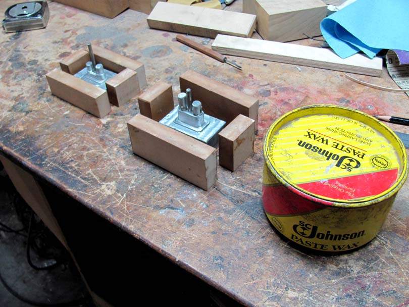
A couple of clamps squeeze the blocks around the Masters. I mix up some silicone mold compound and pour each box up to the top edge.
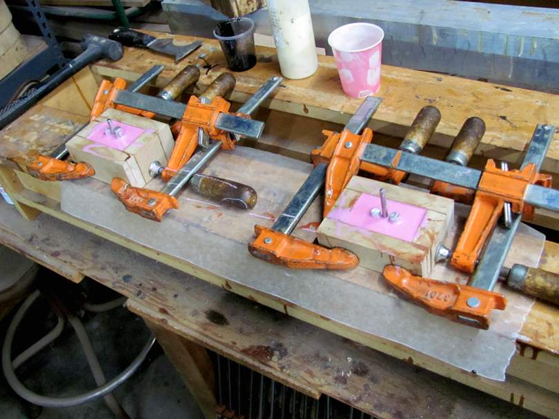
After the silicone has cured, I pull them apart. The silicone compound I used is Smooth-On's Mold Max 30. Here is a pair of molds...
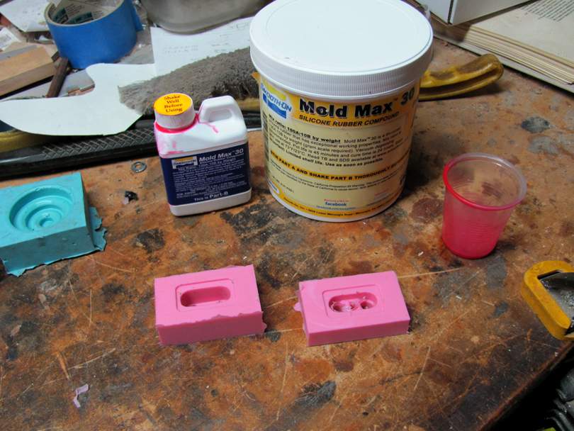
First, I made up a new Master from which to make the molds. I drew it up in Cad, and machined it from aluminum as I had before.
The Master starts out as a block of 1 1/2" x 1 1/2" square 6061 aluminum bar stock. Clamped in the vise of the mill, drilled the holes, milled away the sides....
Here it is roughly milled....
Hand filing the radiuses on the ends and around the flange.....
A light polishing, and it's ready. This is an extended height bobbin half, for a new model of my pickup that uses 3/8" x 1" magnets. The other Master on the right is for the standard height lower half. I made it around 2010. Now, I upgraded it by precisely drilling the holes for the magnets and center pin. I'll show you why below.
Preparing to cast the molds....I cut sets of MDF blocks that fit snug around the base of the Masters.....
Notice the pins in the holes in the Masters.
The Masters, pins and MDF blocks get a light coat of Johnson's Paste Wax....
A couple of clamps squeeze the blocks around the Masters. I mix up some silicone mold compound and pour each box up to the top edge.
After the silicone has cured, I pull them apart. The silicone compound I used is Smooth-On's Mold Max 30. Here is a pair of molds...
Now as I said, this doesn't take into consideration the strength of the magnet
Neo magnets like you're using are probably much stronger than the alnico or ceramic magnets in most pickups, so you might not be as far off as you think. How do they sound?
Here's the new, exciting part:
I made those holes in the mold so that I could use Shoulder Screws as part of the mold, to make the magnet holes accurate size and alignment. Shoulder Screws, also called Stripper Screws, are used in tool & die making. Their main shank is precision ground to an accurate diameter. I got some that are 0.375" dia x 1" long. The thread at the bottom is 5/16"-18.
I machined up an aluminum base block to go under each mold, which has those threaded holes at an accurate spacing and location. Plus the center pin. Here's the set for one mold....
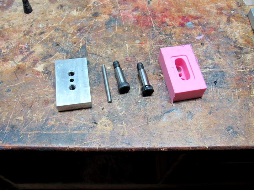
This is how they go together, without the mold on....

To prepare the mold for doing a cast, I start by putting a bead of woodworking glue around the holes on the base block. This acts as a temporary sealant to keep the polyurethane from leaking out around the pin and bolts....
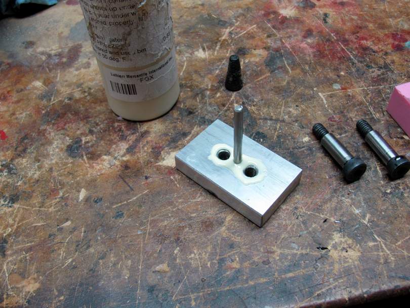
I slip the mold down over the pin and thread the Shoulder Screws down into the base...
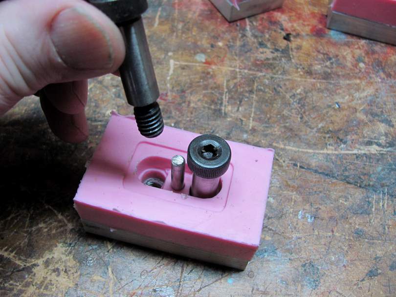
And here's the mold assembly, ready for pouring....
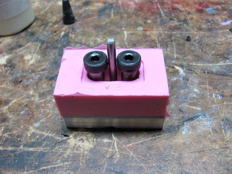
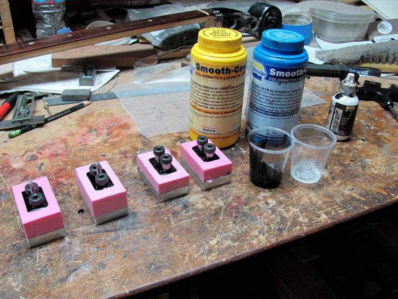
Four of the molds lined up. I mix up some polyurethane casting resin with black pigment in it, and pour it into the molds.
I made those holes in the mold so that I could use Shoulder Screws as part of the mold, to make the magnet holes accurate size and alignment. Shoulder Screws, also called Stripper Screws, are used in tool & die making. Their main shank is precision ground to an accurate diameter. I got some that are 0.375" dia x 1" long. The thread at the bottom is 5/16"-18.
I machined up an aluminum base block to go under each mold, which has those threaded holes at an accurate spacing and location. Plus the center pin. Here's the set for one mold....
This is how they go together, without the mold on....
To prepare the mold for doing a cast, I start by putting a bead of woodworking glue around the holes on the base block. This acts as a temporary sealant to keep the polyurethane from leaking out around the pin and bolts....
I slip the mold down over the pin and thread the Shoulder Screws down into the base...
And here's the mold assembly, ready for pouring....
Four of the molds lined up. I mix up some polyurethane casting resin with black pigment in it, and pour it into the molds.
Neo magnets like you're using are probably much stronger than the alnico or ceramic magnets in most pickups, so you might not be as far off as you think. How do they sound?
To be honest, I'm not sure
The EMG40s are on a bass that I converted to fretless when I was young and naïve. So considering it's a fretless and has a million years old strings, I can say they sound bright and loud when going through a preamp with 2× gain.
The PJ is really bright sounding. It sounded promising at first, but the 3D printed cover of the J part broke, so it's just a P bass. Still very bright sounding, and loud I guess. Again going through a preamp with 2× gain.
I haven't really tried to measure the total resonant frequency of either pickup models yet. Without the filter preamp they did sound bright, but.... I suspect that the resonant frequency might be so high, that they were missing something for me. Kinda hard to express in words. So I just skipped the passive test and connected to the preamp right away.
Anyways, as soon as I fix the J pickup and get some new bobbins, I'm gonna get some clips up. So I don't have to write a page long description of a sound I cant describe
After the polyurethane is cured, I turn the bolts out and pop the parts out of the molds.
Here's one of the extended bobbin halves, right out of the mold...
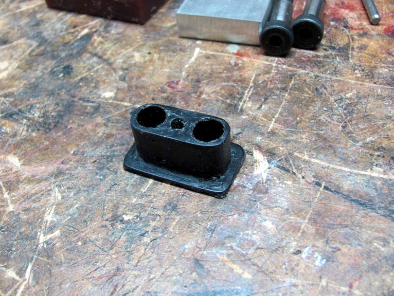
I lightly sand the back face of the flange on the edge sander, and clean any excess off the perimeter of the flange. Then I hand turn a 0.376" reamer through the magnet holes.

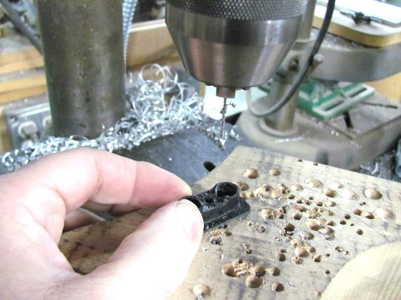
I drill the tiny holes for the terminals, in the little spots left by the molding....
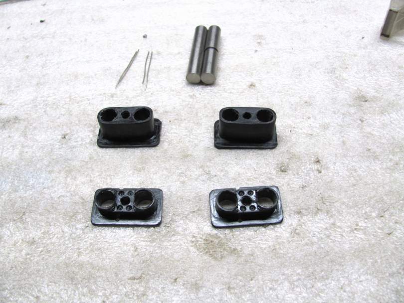
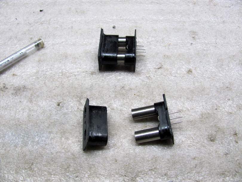
Here's a set of the cast bobbin halves, with the magnets and terminal wires...
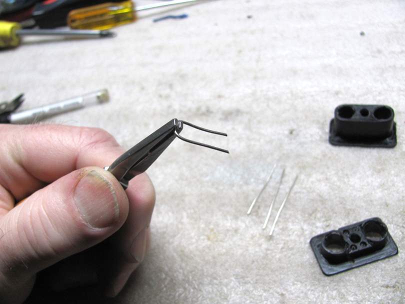
I bend the wires into a narrow U-shape.....
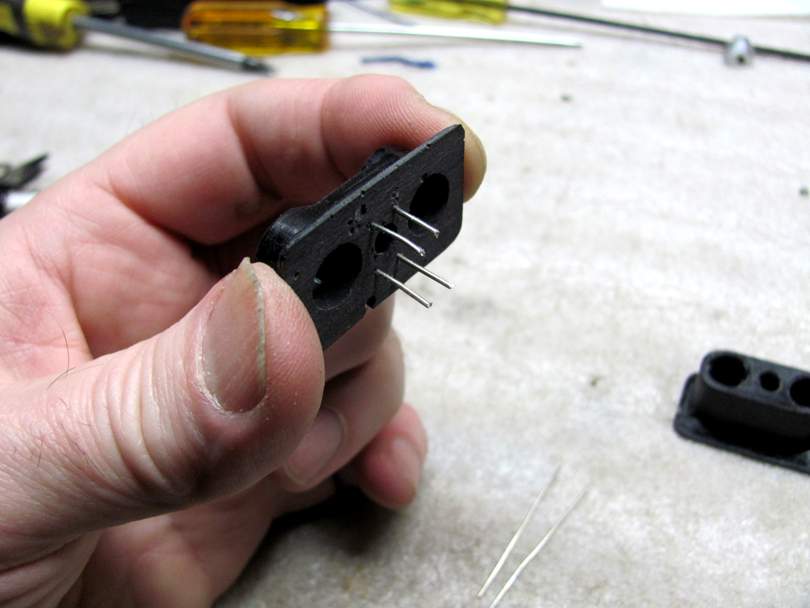
And insert them into the lower half....
Then assemble the bobbin halves onto the magnets. They are a nice sliding fit.
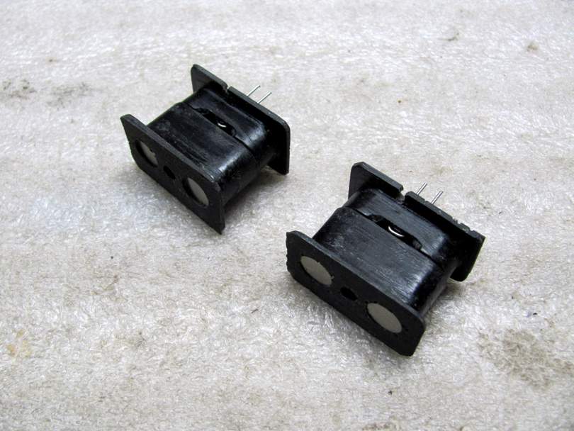
Two bobbins, one with the magnets North Up, and the other South Up.
A quick wrap of Scotch tape around the center, so the wire won't fall into the gap between the bobbin halves...
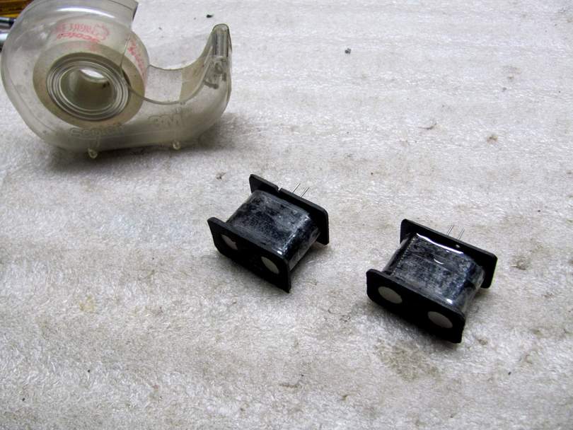
And this pair of bobbins are ready for winding! After winding and potting, I'll push the magnets slightly offset to fit a 7 1/4" radius profile.
Here's one of the extended bobbin halves, right out of the mold...
I lightly sand the back face of the flange on the edge sander, and clean any excess off the perimeter of the flange. Then I hand turn a 0.376" reamer through the magnet holes.
I drill the tiny holes for the terminals, in the little spots left by the molding....
Here's a set of the cast bobbin halves, with the magnets and terminal wires...
I bend the wires into a narrow U-shape.....
And insert them into the lower half....
Then assemble the bobbin halves onto the magnets. They are a nice sliding fit.
Two bobbins, one with the magnets North Up, and the other South Up.
A quick wrap of Scotch tape around the center, so the wire won't fall into the gap between the bobbin halves...
And this pair of bobbins are ready for winding! After winding and potting, I'll push the magnets slightly offset to fit a 7 1/4" radius profile.

@Bruce Johnson I love the casting process and I have seen it used for all kinds of applications including finished pickup covers. Because you design in CAD anyway, and now that you have seen the HP MJF 3D printing process, do you feel this process is something you will continue with? I can completely understand how it can be a satisfying way to create a new and unique part.
@Bruce Johnson I love the casting process and I have seen it used for all kinds of applications including finished pickup covers. Because you design in CAD anyway, and now that you have seen the HP MJF 3D printing process, do you feel this process is something you will continue with? I can completely understand how it can be a satisfying way to create a new and unique part.
That's a fair question, but yes, I plan to keep making my pickup bobbins by this method for many years. Now that I have the tooling made and the process worked out, it takes me very little time to make up a set. It's in the range of 10 minutes to make up an instrument set of bobbin halves. My cost, in materials and my labor, is probably around $7 per instrument set. Having them 3D printed wouldn't be that much less. And, if I make them myself, I don't have to spend the time ordering, receiving, and waiting on someone else's schedule. I can make how many I want, whenever I want.
Remember that the big reason why I make almost all of my own hardware and parts is that I'm creating a job for myself. I'm getting paid to make up bobbins, as opposed to spending money to pay someone else to make them, and then trying to recover that money in the overall sale of the finished instrument. My overall goal is to be a manufacturer, to get paid for personally building basses. I don't want to be a distributor of things other people build. I don't want to subcontract anything unless it's really impractical for me to do it myself.
Last edited:
Now, someday down the road, if I found a used outdated 3-D printer machine for cheap......
Ok since you guys asked for it, I'm gonna share what I've done with my project so far..
Introduction:
I've always been obsessed with reverse engineering and building things that I can't afford. Some time ago I got the idea that I wanted to get a sound like Justin Chancellor (Wal bass, band: Tool), and therefore set on an "epic" quest to build something that will get me close to that. Electronics is my profession, so that part was okish, but I suck big time in mechanical engineering, or building anything that needs at least some "mechanical" skills. Skipping some 10 years to the present, I picked up this project again and this is what I have so far.
Cover no.1:
My original idea was to make a wooden cover. If done right, it would look cool, and be easier to align the bobbins right under the strings. Also it being a soapbar pickup, I thought it sould be pretty easy to cot out a block of wood. I was wrong of course, and abandoned the idea for now. Also it was a pain to work with wood considering all the bobbin and magnet changing and stuff. Here is a prototype cover made from a random branch of walnut from a local forest.
View attachment 4590252View attachment 4590292
Bobbins:
For the bobbins I used a threaded insert for the centre pillar and ordered circular PCB's for the plates at the end. The thread would ensure that the pole piece, which is a M4 screw is held in place and can be height adjusted if needed (inspired by pictures of Wal pickups of course). The PCBs have pads on them so I can solder the pickup wire directly to them. The pads are also large enough so I can solder lead wire to them. It's glued together with epoxy.
View attachment 4590311
Due to the crappy glue job resulting in an uneven centre pillar and the wobble in the winding machine, they didn't end up "perfect" the first time.
I tried a version where I threaded some plastic spacers and glued with CA glue. The end results were prettier. But the bobbins had structural issues, as apparently CA glue doesn't stick so good to PCB's as epoxy does.
View attachment 4590337
All in all, I managed to fit 5000 turns of AWG43 wire. Each coil has a DC resistance of 850Ohm. I measured the resonant frequency of the coils and it's around 80kHz (I should repeat that with better settings to get a super accurate measurement). I still have no clue what would be the total resonant frequency when I connect them in the pickup.
Cover no2. and magnets:
In the mean time I decided to equip my PJ bass wit multi coils as well. Since making P and J pickups out of wood is impossible for me, I turned to to 3D printing. I made Covers for the P and J as well as for the EM40s for my original bass.
I also opted to ditch the headless screws and get cheese head screws so I get a wider sensing area under the string. I have no idea if that's going to make any difference, ut it looked cooler to me
For the PJ I installed ring magnets. The only ones I could get off ebay were the ones wit a screw hole, which is something I'm not happy about - I'd like real rings. The problem is that they fly all over the place, so I needed to fasten them with a nut. At least until I glue them, and fill in the cover with epoxy.
For the EMG40, I 3D printed a plate that holds small cylinder magnets and just fits in the main cover. The magnets don't have physical contact with the pole pieces, but it shouldn't be a problem, I mean they do work ;D
View attachment 4590354 View attachment 4590355
View attachment 4590356 View attachment 4590357 View attachment 4590358 View attachment 4590359
View attachment 4590360 View attachment 4590362
End results:
They all work. I tried to do use filler spray on the plastic to get it smooth and do a paint job, but that came out reeeeeealy bad and I don't have photos of that.
I tried various combinations with the wiring, but it was a real pain with the current magnet configuration, so I just settled with all series for the PJ (wired in humbucking mode), and one humbucker per string for the EMG40, then all summed in an active buffer.
What next?:
I'm going to try getting PA12 Nylon bobbins made in China and try to get more windings in there.
I'd like to find some "normal" sized bar magnets, so I can make steel keepers for the pole pieces like every other normal human being does. This seems overly complicated so far.
Id like to revisit my idea of wooden covers, but I'll need better magnet solutions for that.
Also, any other good ideas would be appreciated.
I think your prototypes look really good! I commend you for taking on a difficult pickup design.
Here's my take, and you can follow it or reject it - that's up to you. Keep in mind, I've never made a Wal-style multicoil myself, but I have experimented a fair amount with neodymium magnets. In your case especially, those neos, more than anything, are going to be a real PITA. They're hard to manage, and once you start wrapping more wire on them, they start to get real dark sounding.
From what I understand, (I'm sure others with more experience @MPU @slowburnaz can chime in) the Wal pickup is a pretty tried and true design of 10000 turns of #42 around each coil. I'm not sure if they use AlNiCo cylinders or a ceramic bar magnet, but either one would work fine.
If this was my project, and I was trying to execute a complicated magnetic structure like a Wal multi-coil, I would probably opt for a more streamlined approach and use C8's or AlNiCo 5 magnets rather than struggle with the neos. It's not to say that it can't be done or that you won't be able to do it. It is to say that making these pickups with neodymium magnets is going to be a lot more difficult, and the end result won't be radically different from the results you would get from a different magnet.
One other thing - all those other extra bits of metal - the threaded inserts and the keeper nuts on the bottom of your coils - you want to minimize the use of magnetic and conductive materials. Keep in mind that all these thing will have an affect on the sound - whether or not that is your intention is another issue. Seeing those nuts ring alarm bells in my mind. Personally, I try to think in terms of how I'm shaping a magnetic field wrapped in electrical current. A better option would be to have those screws thread into a single steel bar. You can then use that bar to attach your magnet. Another approach I've seen guys do is use a PCB with holes into which non-threaded pole pieces can be press fit.
The threaded inserts - they also appear to be made of metal, which is not optimal. Not only that, they take up a lot of space where you could be wrapping more wire. You're using up a lot of your wire channel with those inserts. I'd recommend just wrapping the wire directly around an insulated pole - be it a steel slug or AlNiCo cylinder - and use flatwork on the top and bottom to make a bobbin.
Other than that, your engineering looks very neat and tidy. Certainly much neater that I could do. I hope this helps.
Last edited:

I imagine this also relieves some vulnerability to those supply chain issues we keep hearing about. A gallon of molding compound for building components might be as hard to get as finished components are, but you won't have to order new molding compound if the component specs change.I'm getting paid to make up bobbins, as opposed to spending money to pay someone else to make them, and then trying to recover that money in the overall sale of the finished instrument. My overall goal is to be a manufacturer, to get paid for personally building basses. I don't want to be a distributor of things other people build. I don't want to subcontract anything unless it's really impractical for me to do it myself.
Vintage 3d-printers are soooo hard to find.Now, someday down the road, if I found a used outdated 3-D printer machine for cheap......
Now, someday down the road, if I found a used outdated 3-D printer machine for cheap......
A boy can dream, right?


