• TalkBass has been independent since 1998. Add your voice.
    Create a free account to reply to discussions, view embedded media, and browse with fewer display ads.
    Join freeLog in
    Want zero display ads or expanded classifieds tools? Compare plans.

Medium scale, semi-hollow, single cut bass w/ CNC content

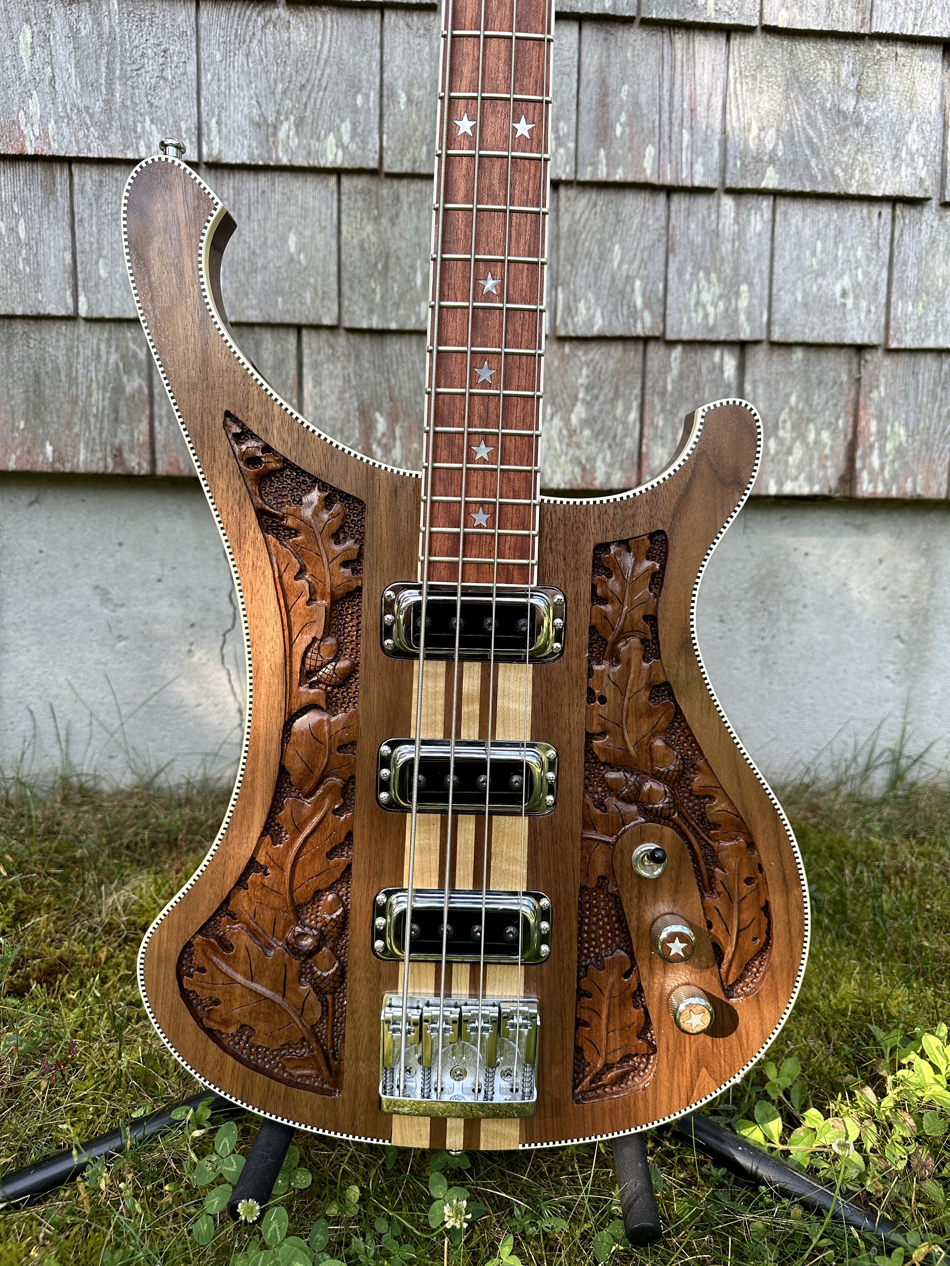
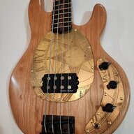
These MOP star inlays kicked my a$$! In retrospect, CNC might not have helped much, since these were hand-made in Vietnam, so each one effectively unique. Ideally you'd cut these out of MOP sheet stock using the same CNC pattern for the recesses. Including the knob inlays, I think this took me the better part of two days of eye strain and aching hands vs. something like minutes for CNC.
1WDiPfk.jpg
The star inlays look amazing, I love how that bass turned out! I do not envy you the inlay task, though. My hands would not make it through that endeavor.
 
That's a good idea. Maybe nut slotting files would work for that; smooth sides so I could lengthen the slots without inadvertently widening them?

If you have the nut files they’ll definitely work but you could also do it carefully with a needle file or a hacksaw blade or two. Even the ever popular sandpaper wrapped around the appropriately sized drill bit.
 
  • Like
Reactions: BishopJP
Unrelated to bass building, the missus and I took a short trip to Asheville the this weekend to see Idles perform.
Resized_20240914_213616_1726612935769.jpeg

Gear of note: the bass player sometimes plays a Serek bass (not shown here) and the guitar player (on the left) is playing an Aluminati guitar, made locally in Asheville. The Aluminati guitar has an aluminum neck and a clear lucite body. Kinda cool!


Back to building...

Not letting the machine do ALL the work, I took the offcut from the fretboard and resawed it the hard way...
20240903_112300.jpg20240903_120511.jpg
...bookmatched, glued up, to make a headstock veneer.

Then, I let the machine thickness it and cut it out for me...
20240904_093920.jpg 20240904_093932.jpg
...little bit of chipping at the glue joint I didn't see until it was finished. I should be able to sand it out.
 
Continuing with the neck...

Drilled the neck for side and face dots, both will get 1/8" aluminum tube with white plastic inner...
20240910_1739201.jpg20240910_174451.jpg
...pre-cut the pieces and tap them in along with a little CA glue.

When drilling for face dots, I found out that the 17th fret marker was directly over one of the threaded inserts inside the neck...
20240910_181104.jpg
...and I drilled right through! No damage to the threads, the drill bit was nicely centered.

No big deal; plug the hole, glue in the dot and chase the threads in the brass insert after the glue dried.

After the dots are in, the neck goes back in the neck jig to radius the fret board...
20240916_120334.jpg


After routing, a little cleanup sanding...
20240916_120608.jpg


Then it's time for oil...
20240916_124535.jpg
...the walnut looks a lot brighter in this pic than I think it is IRL.
 
And the frets are in...
20240923_130023.jpg


I neglected to get any pics, but my process is as follows

-Frets are radiused, cut to length and the tangs cut back
-Fret board gets oiled around the slot I'm working on, to resist glue
-CA glue in the slot
-Fret gets pressed in using the arbor press and the J. Edwards "fractal fret press" I recently acquired. That thing is too cool!
-Fret ends trimmed, filed and beveled

Pretty sure everyone has seen it numerous times before.
 
This little guy...
Screenshot 2024-09-24 at 12-26-50 The Fractal Fret Press for compound & standard radius fretbo...png..pic from the website.


It's not cheap and might seem a bit of an extravagance but it works really well. With this, you don't need to buy different cauls for different radii or if you are doing a multi scale or a fretboard with a compound radius.
 
With the top-to-back thickness where I want it, I can start shaping the back of the neck.

Using the facet method, I carve a short facet at the head and at the heel with the shinto and other rasps...
20240923_171112.jpg 20240923_171924.jpg
...then connect the two with a spoke shave and a block plane where possible.

Then I attached the neck to my neck-holder-beam thing, which I should have done at the outset, and started the secondary facets...
20240924_111401.jpg 20240924_111418.jpg
...I also use this cheap, little plane for smoothing out the neck. It works surprisingly well for knocking down the high spots.

Then I start the tertiary facets, which quickly turns into rounding out the neck...
20240924_121439.jpg
...here its at about 90% after some sanding with 120 grit.

At this point, I'll start roughing in the volute...
20240924_142926.jpg
...the back of the headstock is little ugly. You can see the seam where I glued up the scarf joint; looks like I did not get good pressure at that spot. Maybe I'll put a veneer on the back, too.
 
Working on the body and accessories...

I wanted to make wooden knobs for this build. I have made them before, using the drill press, this time I used the CNC.

I had previously glued up a couple cherry scraps layered with a black veneer, total thickness approx .6". I stuck the scrap down with tape and CA glue and started the operations...
20240930_120455.jpg
...these took 4 operations:
1 - drill holes with 1/4" ball-nose end mill to create the flutes
2 - drill the hole for the pot shaft, sized to fit an aluminum sleeve
3 - pocket the recess for the inlay
4 - route the contour

Of the 5 shown, 2 had chip-out at the upper edge, right where you would expect.

Side note: this could all be done with a drill press, following the same steps, except for the last step you would use a hole saw or plug cutter.

After removing them from the machine, I used CA glue to glue in the aluminum sleeve. The aluminum has an ID of 1/4", which is necessary for the the next step...
20240930_130244.jpg 20240930_151106.jpg
...the knob gets clamped in the mini vice and drilled with a counter-bore attachment on a 1/4" drill bit.


The walnut circle inlays were cut out on the CNC from the same veneer I used for the headstock overlay...
20240930_151134.jpg 20240930_160126.jpg
...my tolerances were slightly off so I had to do some sanding to get the inlays to fit.

Again, I have also cut circular inlays with a drill press using a plug cutter.


I will be making a pick-up for this build; it's not finished, but here is the cover...
20240930_160213.jpg 20240930_160223.jpg
...cut from a scrap off walnut, it is approximately P90 sized.
 
Now for the scary part...

I didn't account for the controls and control cavity when I initially cut out the body because I wanted to see the parts in real life first. Figuring it out in a CAD design doesn't always give you an accurate impression of scale and proportion.

So, I had to take the chance of putting the body back in the machine, spend 20 minutes aligning the body...
20240930_172131.jpg
...and drill the pot holes and knob recesses. And everything was fine!

Next was the control cavity on the back. Same lengthy process of aligning the body...
20240930_175702.jpg 20240930_180432.jpg
...this went fine as well, except I miscalculated and the lip for attaching the cover wound up a little thin. I will probably cut a piece to glue in and thicken up the lip a little.


And here is the body as it is now...
20240930_180129.jpg

...showing the new knobs, the pick-up cover and the Hipshot D-Style bridge.
 
Time for tuners...
And their requisite holes in the headstock...

First, I drilled 1/16" pilot holes, then followed that up with a 3/4" paddle bit...
20241008_153357.jpg...I wanted a slight recess so I drilled through the walnut until I hit cherry. I normally would use a forstner bit, but all mine have the cutting edges at the outside of the bit. Luckily, I happened to have a paddle bit with square corners.

Flipped the headstock over and drilled from the back with a 9/16" brad point bit, following the 1/16" pilot hole...
20241008_154603.jpg...stopped short of drilling all the way through, hoping to avoid and blowout.

Used a step-bit to clean up the onion skin left behind...
20241008_154854.jpg...and put a tiny chamfer on both sides of the hole.

And tuners installed!
20241008_155833.jpg

Still need to drill for the mounting screws on the back, but I need to figure how I want to angle the tuners first.
 
Little update on this build, working on the pickup...

The pickup is not a radical new design, just a simple single coil. Kind of a mashup of a '51 P and a P90.

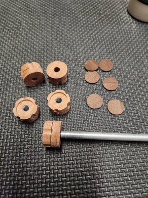
First, I made the bobbins, I made a few just in case. Materials on hand were 1/2" plywood scraps and 1/16" garolite...
20241012_204546.jpg...I used the CNC to make the top with an integrated spacer out of the plywood. This ply is pretty low-void, not like construction grade wall sheathing.
The bottom was made from the garolite.
The bobbin pieces have holes routed for the pole pieces and mounting screws.

20241012_205140.jpg
...I tapped the holes for the M5 machine screws which will be the pole pieces. I also put eyelets in the holes for the leads. With the bobbin pieces glued together, it was time to wind.

Unfortunately, I hit the end of the spool of wire at about 5500 turns...
20241027_151109.jpg
...not wanting to waste the winds and it's for my personal use, I spliced wire from a fresh spool. Small piece of masking tape on the coil, then I soldered the end of the wire to a piece of copper shielding tape, then soldered the new spool to the tape as well.

Then I stuck it to the coil and kept winding...20241027_153355.jpg
...you can't even tell! I also attached the leads and checked for continuity
All good!
Forgot to get a pic (I'll add one later) but wax potted in a crock pot then installed the M5 pole pieces and 2 ceramic 8 bar magnets to complete the pickup.

Pic of the completed pickup coming soon...
 
Little update on this build, working on the pickup...

The pickup is not a radical new design, just a simple single coil. Kind of a mashup of a '51 P and a P90.

First, I made the bobbins, I made a few just in case. Materials on hand were 1/2" plywood scraps and 1/16" garolite...
View attachment 7066522...I used the CNC to make the top with an integrated spacer out of the plywood. This ply is pretty low-void, not like construction grade wall sheathing.
The bottom was made from the garolite.
The bobbin pieces have holes routed for the pole pieces and mounting screws.

View attachment 7066523
...I tapped the holes for the M5 machine screws which will be the pole pieces. I also put eyelets in the holes for the leads. With the bobbin pieces glued together, it was time to wind.

Unfortunately, I hit the end of the spool of wire at about 5500 turns...
View attachment 7066524
...not wanting to waste the winds and it's for my personal use, I spliced wire from a fresh spool. Small piece of masking tape on the coil, then I soldered the end of the wire to a piece of copper shielding tape, then soldered the new spool to the tape as well.

Then I stuck it to the coil and kept winding...View attachment 7066525
...you can't even tell! I also attached the leads and checked for continuity
All good!
Forgot to get a pic (I'll add one later) but wax potted in a crock pot then installed the M5 pole pieces and 2 ceramic 8 bar magnets to complete the pickup.

Pic of the completed pickup coming soon...

Now when people like the sound of your bass you’ll have to claim its the pickup splice and tone masking tape. :smug: :thumbsup:
 
from an aesthetic perspective, I feel like the top should have another bevel to match the forearm bevel.
Trust your gut instinct.

Unless you are going for minimalist functionalism, respect your own sense of what's aesthetically correct. Which would be the minimalist option if you felt that way. So it sounds like some tedious realignment/remounting and another bevel is in your future. IIRC this is a prototype, so if you build it that way and don't like it after all, you comment out that section of code next time.
 
  • Like
Reactions: BishopJP
Trust your gut instinct.

Unless you are going for minimalist functionalism, respect your own sense of what's aesthetically correct. Which would be the minimalist option if you felt that way. So it sounds like some tedious realignment/remounting and another bevel is in your future. IIRC this is a prototype, so if you build it that way and don't like it after all, you comment out that section of code next time.
You are correct in that minimalist functionalism informs my design aesthetic and also it is a prototype so if I don't like it I can change the next one. Both good points!

The good news is I routed the levels on the router table so I won't have re-set the body on the CNC. Still tedious, but not as tedious...
 
  • Like
Reactions: 41Hz To Go