• TalkBass has been independent since 1998. Add your voice.
    Create a free account to reply to discussions, view embedded media, and browse with fewer display ads.
    Join freeLog in
    Want zero display ads or expanded classifieds tools? Compare plans.

Mesa/Boogie D-180

I just got a Boogie D-180 and wanted to see if anyone on here could enlighten me about it. I apologize for the poor images, and I can try to post some better ones with another camera later if needed. Boogie support hasn't been overly helpful with my questions so I thought I would check with you guys. The amp appears to have most of what I assume are original Philips 6550s, 2 have been replaced with Groove Tubes 6L6s. The pre-amp tubes are all Ruby 12AX7s, which I don't believe are original and I think at least one should be a 12AT7. There are no labels or markings anywhere on the chassis to indicate what tubes it should have or where. Also the serial number is D701 which seems to be outside of what is listed for production on Boogie's site. A couple questions: which pre-amp tube slot(s) should have a 12AT7 and is it okay to run 6550s and 6l6s together? Any other interesting facts I should be aware of would be most welcome, too.
IMAG0308 (2).JPG IMAG0309.JPG
 
  • Like
Reactions: Ellery
Congrats on the amp! I just got one a month ago and love the master limiter in order to get some overdriven tones.

Some notes:
-Channel 1 cascades into channel 2. Plugging into channel one can create some crazy overdriven tones.
- Channel 1 was designed for guitar.
- Channel 2 for bass.
- Keep the master at 10 for clean tones. Anything lower and the amp will start to overdrive. I’ve found 8-9.5 are usable.

The amp should not run on 6550s and 6l6s simultaneously. I won’t recommend turning it on or you’ll blow a fuse, tube or transformer. I’ll leave the technical explanations to someone else.

Did you get one with a graphic EQ? I can’t tell from the pics. Upload some better pictures and we can help you with the preamp tube question.
 
Last edited:
  • Like
Reactions: David Lancaster
I just got a Boogie D-180 and wanted to see if anyone on here could enlighten me about it. I apologize for the poor images, and I can try to post some better ones with another camera later if needed. Boogie support hasn't been overly helpful with my questions so I thought I would check with you guys. The amp appears to have most of what I assume are original Philips 6550s, 2 have been replaced with Groove Tubes 6L6s. The pre-amp tubes are all Ruby 12AX7s, which I don't believe are original and I think at least one should be a 12AT7. There are no labels or markings anywhere on the chassis to indicate what tubes it should have or where. Also the serial number is D701 which seems to be outside of what is listed for production on Boogie's site. A couple questions: which pre-amp tube slot(s) should have a 12AT7 and is it okay to run 6550s and 6l6s together? Any other interesting facts I should be aware of would be most welcome, too.

Was this the amp on Reverb?

Unfortunately there were multiple preamp revisions. Some had 12AT7 and some did not. There may be a label on the chassis and/or stamps next to each tube socket.

Mesa D180/400 Tube Question
Mesa D180 preamp tubes

Barring labels or stamps, you will have to resort to tube rolling and decide which tube type sounds best. It should be safe to swap 12AX7 with 12AT7 and vice versa. I knowledgeable tech could probably look at a few resistors on each tube circuit and determine what tubes the amp is setup for, but I can't say for sure if Mesa rebiased the circuits when the tube types were changed. Possible locations for 12AT7 are V2 and V3.

The amp will run either 6550 or 6L6 but I believe these tube types typically require significantly different bias voltages, so it's suspect for the amp to have both tube types. I wouldn't run the amp without confirming the bias for all output tubes is within a safe range. If the quiescent current is relatively balanced in the proper range across all of the tubes, I would feel comfortable running mixed tubes.

The amp did not come from the factory with adjustable bias. If the amp is stock, you can buy a set of 6L6 tubes graded to work and bias properly from Mesa. I don't believe Mesa currently sells 6550s and I don't know if they have a set of KT88s that will run in the amp. I have read that some other tubes vendors can match up a set of tubes for this amp.

If the amp has been modded with a properly functioning adjustable bias control, it should safely run with either a matched set of 6L6GC or 6550s.

I believe 6550s will make slightly more power. The tone is a bit different, especially if the amp is pushed into output drive. I get the impression people prefer 6L6GC in this amp as the tone and OD is a bit sweeter

The Master volume is unusual in this amp. If you want max clean power, run the Master wide open. If you dial the Master back, the amp is designed to distort at a lower volume. This is achieved by starving the driver tubes of current. So you basically trick the amp into emulating push/pull output drive, but the distortion is actually occurring in the driver tubes instead of the output tubes. The transition from clean to OD occurs over a fairly small range of adjustment of the Master Volume control...a fraction of a turn.
 
Last edited:
Hello, I have a D-180 and while most production versions run on a sextet of 6l6gc tubes, there was at least 1 ad with Randall talking about the amp having 6550 tubes in it. Which ever this version is, it will run either or, not a mix of both.
Regarding the preamp tubes, I was told by a mesa tech here in LA that regardless of what the labeling is, you could put all 12ax7 tubes and it will run fine. Mine is 12ax7/at7/at7/12ax7
i have seen some that are all 12ax7’s. Someone on the d-180 thread confirmed this also.

If you need a sextet of 6l6gc tubes, I bought a set of winged C’s from tubedepot and told them it was for a mesa, they matched a set, I recall he said mesa runs their tubes kind of cold. That was about 6 years ago, and have not had a failure with them. It’s a solid reliable amp, a work horse if there ever was one.

Mine is from 82 and came with original set of sylvanias which are in my mesa buster. Other than changing out the power switch and the bass capacitors at boogies recommendation , I don’t think it has had any other work done. How many amps can you say that about?
 
What should be considered in the conversation about 6L6GC and 6550 tubes is the difference in heater draw. The 6L6GC draws 0.9A each against the 6550 1.5A. Across six tubes that’s 3.6A the power transformer was not designed to supply..


That's a valid concern with some amps, but it's not a problem with the D180. The D180 will run fine with 6550s you just need to adjust the bias. There are multiple posts throughout Talkbass where people have called Mesa and confirmed this. Here's an example: Mesa D180/400 Tube Question

I believe most people who have tried 6550s say they prefer the sound of 6L6GC.
 
The Master volume is unusual in this amp. If you want max clean power, run the Master wide open. If you dial the Master back, the amp is designed to distort at a lower volume. This is achieved by starving the driver tubes of current. So you basically trick the amp into emulating push/pull output drive, but the distortion is actually occurring in the driver tubes instead of the output tubes.
I thought that had been debunked and it's actually a solid state circuit doing the clipping?
 
I thought that had been debunked and it's actually a solid state circuit doing the clipping?
I just looked at the schematic and there isn't a single solid state device in the whole amp.

[edit: for accuracy, there are a couple of constant current diodes, but they are used for biasing purposes and have nothing to do with clipping behavior at normal operating levels]
 
Last edited:
  • Like
Reactions: 31HZ
I just looked at the schematic and there isn't a single solid state device in the whole amp.

The PI and Drivers have a constant current diode (TCR508) connected common cathode. I believe the current spec for TCR508 is 2.1ma. I assume the driver tubes clip when a huge resistance is introduced into the cathode circuit via the Master Volume control. I have never dealt with constant current diodes, so I don't know how they behave when the current drops below spec.

What roll does the TCR508s fill in the PI and Driver circuits?
 
Thanks for the help guys. I believe someone has been into the chassis of this one, the pilot light is kind of off-center and the standby switch doesn't function (always on). I believe the fuse holder has been changed because it's blocking the rating below it. It has a 15 amp fuse in it! What is the rated value supposed to be? I believe I will switch it to all 6L6's before I fire it up again. It seemed to run fine other than having some light intermittent popping in the background (probably moisture in the filter caps). I couldn't get the gain to cascade on channel one with a guitar, though (channel 2 volume had no effect only channel 1 volume made a difference.)
 
  • Like
Reactions: Wasnex
The PI and Drivers have a constant current diode (TCR508) connected common cathode. I believe the current spec for TCR508 is 2.1ma. I assume the driver tubes clip when a huge resistance is introduced into the cathode circuit via the Master Volume control. I have never dealt with constant current diodes, so I don't know how they behave when the current drops below spec.

What roll does the TCR508s fill in the PI and Driver circuits?

I should have been more accurate and specific, the constant current diode is actually a monolithic FET circuit that changes resistance in order to hold a constant current through it (I recall it being a couple of mA). It's no different than a constant current source used in all kinds of amplifier biasing. Holding the bias current constant means that the natural variation in the tube's operating point will be automatically corrected for, this is exactly how it's used in the first stage.

In the second stage it's used the same way when the master volume is turned up most of the way (the current source dominates the operating conditions), but as the master is turned down, the current source drops outy of the equation and the bias drops on the final PI/inverter stage as well as the AC & DC feedback increases which reduces the audio level. Because of the location of the master volume pot, the distortion changes with lower levels of the control. The constant current source really only comes into play when the master is turned up, because with the master turned down it looks more like a simple resistor. I don't see how it could have any effect on the power amp clipping, though the master volume itself in that location certainly can. In fact, you could replace the current source with a resistor of maybe 1.5k-3k and the circuit should still function the same (I don't recommend it though)
 
  • Like
Reactions: kranahan and Wasnex
I just looked at the schematic and there isn't a single solid state device in the whole amp.

[edit: for accuracy, there are a couple of constant current diodes, but they are used for biasing purposes and have nothing to do with clipping behavior at normal operating levels]
How about the squishy overdrive that is so hard to find in between 10 off and tin of wasps at about 9 on Master?
 
Last edited:
How about the squishy overdrive that is so hard to find in between 10 off and tin of wasps at about 9 on Master?
Since the constant current source saturates below 2mA, the master volume control dominates by increasing feedback. The master volume control in that location could be the cause, but I haven't ever calculated anything out in this kind of circuit other than to understand it's basic operation.

The constant current source "could" be a tube as well, doesn't have to be a FET/diode though obviously a tube is more cumbersome. I have seen some older circuits that used a tube section for this.
 
Since the constant current source saturates below 2mA, the master volume control dominates by increasing feedback. The master volume control in that location could be the cause, but I haven't ever calculated anything out in this kind of circuit other than to understand it's basic operation.

The constant current source "could" be a tube as well, doesn't have to be a FET/diode though obviously a tube is more cumbersome. I have seen some older circuits that used a tube section for this.
I don't know enough to begin to discuss but it sounds a lot like the guy who reckoned the MV control itself was doing all the distortion at the tail of the preamp and the power tubes operated normally at their full potential.
 
  • Like
Reactions: Wasnex
How about the squishy overdrive that is so hard to find in between 10 off and tin of wasps at about 9 on Master?

You may remember that @pmx theorized that replacing the stock Master Volume pot with a 1 Meg reverse log pot would expand the usable range. Here's the post: My Mesa d180...

He also posted part of an article or ad talking about the D180 running 6550s and making over 200W. Here's the post: My Mesa d180...
 
Constant current source bias is used in a lot of high gain and op-amp type circuits, one big benefit is reduced noise from power supply ripple. I'm sure there is some benefit in the output driver circuits because there is voltage gain in both balanced stages. Once the master is turned down and the current source saturates, this benefit disappears in the second stage.

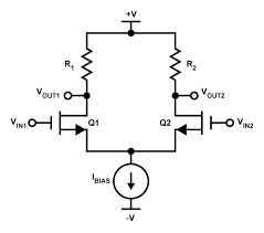
Here's an example of a FET LTP that uses a constant current bias topology, it's almost identical to the LTP driver/PI that's used in the D-180 except that the FETs are really triodes (math is almost the same):
UoHAG.png


Here is the circuit again, but using triodes with a pentode as a current source:
Amp-Long_Tail_Pair-4.gif


Thinking of a way to explain how the master volume control works, it's in series with the constant current source so when the control is turned down, the current falls below the ~2mA and the source saturates. Now, the master volume control dominates everything that happens in the circuit. A wonderful example of this is the principle that a tremolo works on, the amplitude modulation is done in much the same way, by changing the bias current (which also changes the local feedback and gain). Here's something that shows the elements broken out in all 3 topologies courtesy of Rod Elliot. Vary the bias and the gain changes:
Link Removed

Maybe this helps, for those few who might be interested in the principles behind the circuit.
 
Last edited: