• TalkBass has been independent since 1998. Add your voice.
    Create a free account to reply to discussions, view embedded media, and browse with fewer display ads.
    Join freeLog in
    Want zero display ads or expanded classifieds tools? Compare plans.

Mod HPF Pre series 3 to make always on high pass filter pedal

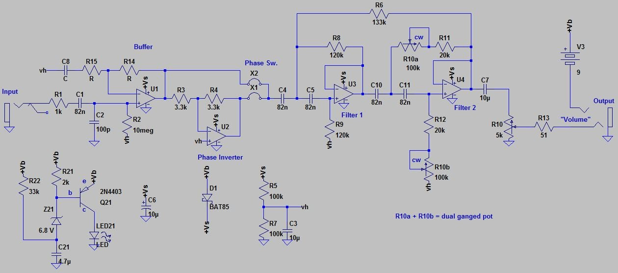
The HPF Pre is a great tool for taming the low end on an upright while simultaneously providing a good high impedance buffer for a piezo pickup. It's a well made and quiet device and the schematic is kindly posted for DIY folks. I'm interested in making a slightly different stripped down version of this to use as an 'always on' high pass filter (HPF) in a sort of modular format that I can use either in a pedal or as part of other circuit designs. This would be similar to a Broughton always on HPF (I have one of these, it's also a very effective and high quality device).
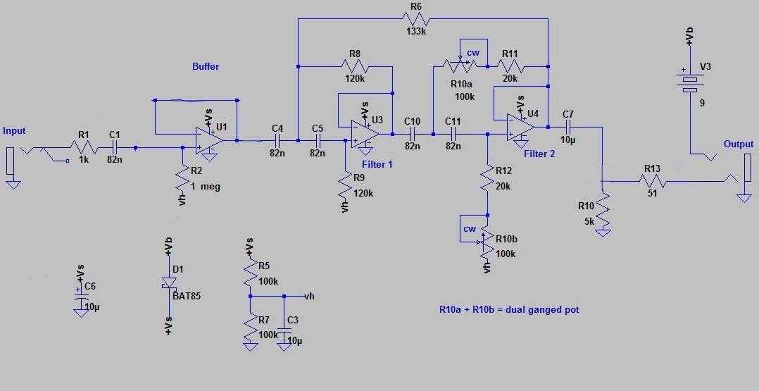
I'm going to post the stock schematic and a proposed modded schematic with the battery indicator removed (I'll power with external DC), phase inverter removed and output volume removed as I just want a unity gain always on HPF.
Stock schem:
pre schem.png


modded schem:
HPFpreV3-mod copy.jpg


I have ordered a set of parts to build this on a small perf board using a TLC2264 quad op amp because the lower noise recommended OPA1654 quad audio JFET op amp is not easily available right now.
I'm wondering if anyone sees any obvious flaws with my modifications. Do I need better power filtering if I plan to use a typical 9VDC pedal power supply? I reduced input impedance to 1M from 10M. I removed any gain from the first opamp but I could put some back in if the output isn't unity gain.
I'll post the result of my prototype build if there are no comments in the next week or so while I wait for parts and put it together.
 

Attachments

  • IMG_20190906_145049.jpg
    IMG_20190906_145049.jpg
    606 KB · Views: 138
  • Like
Reactions: RobbieK
The HPF Pre is a great tool for taming the low end on an upright while simultaneously providing a good high impedance buffer for a piezo pickup. It's a well made and quiet device and the schematic is kindly posted for DIY folks. I'm interested in making a slightly different stripped down version of this to use as an 'always on' high pass filter (HPF) in a sort of modular format that I can use either in a pedal or as part of other circuit designs. This would be similar to a Broughton always on HPF (I have one of these, it's also a very effective and high quality device).
I'm going to post the stock schematic and a proposed modded schematic with the battery indicator removed (I'll power with external DC), phase inverter removed and output volume removed as I just want a unity gain always on HPF.
Stock schem:
View attachment 4573315

modded schem:
View attachment 4573318

I have ordered a set of parts to build this on a small perf board using a TLC2264 quad op amp because the lower noise recommended OPA1654 quad audio JFET op amp is not easily available right now.
I'm wondering if anyone sees any obvious flaws with my modifications. Do I need better power filtering if I plan to use a typical 9VDC pedal power supply? I reduced input impedance to 1M from 10M. I removed any gain from the first opamp but I could put some back in if the output isn't unity gain.
I'll post the result of my prototype build if there are no comments in the next week or so while I wait for parts and put it together.
Looks good to me. ;) Note that the TLC2264 is spec'd for 16 Volts max. That should be fine with 9V battery or 9V regulated power supply, but the old line frequency (typically heavy) wall warts often run much higher than their rated voltage when operating at low current. If you're planning on using a power supply, I suggest measuring its output just to be safe. That's actually one of the reasons I went with the OPC1654.
 
  • Like
Reactions: Jim C
Looks good to me.
Great! I'll put a prototype together on a piece of perf board and see if I can get some signal through it. I'll put the opamp on a socket so I could look into choosing a different one later if there is a need to optimize based on noise, signal level (instrument or line level for example) and supply voltage. I do hear you about the heavy wall warts and the high voltage - loaded down they drop voltage but in this kind of application they can be too high. I try to use only well regulated supplies and I have a bunch so I can test and compare to make sure I'm not introducing noise from the supply.
 
  • Like
Reactions: fdeck
Success!
This is the prototype (I won't show the nasty underside where I did the connections):
prototype1.JPG

Surprisingly it came on and passes clean signal. I used a 9v battery to test and I didn't notice any noise issues. It's unity gain. I did some basic frequency response plots and it gives me what I expected:
HPF.png

With the pot set for 'no cut' I get a -6db cut at 30hz, which is -3db from the first fixed filter plus -3db from the second filter. This is just what the online calculator told me it should do. Rotating the pot I get the response shown - max cut has a -6 db point right about 100hz. I'm going to try changing the two 20k stop resistors to 7.5k so I can get some more cut for guitar applications (or is saying the 'guitar' word a no-no around here?:).

Since I had an empty op amp (was being used by phase reverse section I deleted) I decided to add a low pass filter using the same kind of filter design. This worked out well and gives me just the kind of high freq cut that I'd like for some applications. I used a 10k linear dual pot to test with as it was the only match for the film caps I happen to have but I've put the values I plan to use in the next round in this updated (crude, sorry) schematic (HPF is -6db at 1.5kHz at max cut):
HPFpreV3-modLPF.png

I'm using calculators for the filter design from this site:
Filter Design and Analysis
The response with both LPF and HPF filters looks like this:
overlay full.png

I ordered regular audio taper pots and now I realize I need reverse log pots. I'm ordering some reverse log 100k dual pots from Digikey along with caps and such for the LPF section so it will likely be a week or so before I can do much more. Any ideas/suggestions/comments (and sure, flames) in the meantime are welcome!
I only tested this with low instrument level signal but I hope to be able to also make one that can handle hot line level signal. I probably need a different opamp for this. If anyone has a good suggestion I'd be interested. I'd like to keep it a single supply (as opposed to V+/V-) and in the same DIP socket format (2.54 mm spacing). I could potentially use an adapter though if the only good options come in some tedious to solder tiny format. I'll do a better analysis of the noise floor as well, but as it is I think it's good to go for instrument level signal as long as I have a clean power supply.
 
Second prototype fired up on the first try! Which is semi-amazing when you see the back side of this one....
This second version, also built very compact on a 0.1" spacing perf board, features some proper 100kC reverse log pots that are mounted to the board itself, a OPA1644 opamp, a header for connecting the in/out and power, and a modified set of stop resistors (7.5k) to move the frequency sweep endpoints.

Results are good. Responds correctly (nicer with the reverse log pots), no sound quality issues so far, noise floor is good. So far so good, although tests are not extensive yet. One goal I have with this project is to make two versions of this widget: One mounted inside a tube amp I've built that uses an available 24VDC power supply (this one, the OPA1644 version) and another that is part of an on-board pre-amp for two magnetic pickups (the TLC2264 opamp version). I measured OPA1644 used 6.7 ma of current while TLC2264 used only 0.8 ma. TLC2264 would be ok on battery. I'm working on a pre-amp schematic and I'd incorporate this filter set into it with the TLC2264. I just seem to really prefer HP/LP filters over shelving. The pre-amp is for two passive pickups with each with their own "loaded input buffer" so that it sounds like a passive setup rather than the more bright shiny buffered passive pickup sound. These two buffers go into an active blend (which is where I'm stuck right now because it's harder that I thought to mix two signals without having crosstalk or interactions), and then into this HPF/LPF filter for "bass" and "treble". 4 pots: Volume, blend, HPF, LPF plus two pull switches to change the pickup loading to go from warm to bright. I'll post an update if I manage to get the preamp working with this HPF/LPF in it.

For the in-amp version I will either cover this in shrink wrap or pot the back side with all of the wires. I made it so that I can drill two holes in the amp front panel and mount this directly. I'd put a switch to allow true bypass vs having the signal pass through this before hitting the amp. This is basically no different than mounting it in a pedal enclosure but I intend to use it all the time and I don't want to bother with a pedal/power/cables, etc. OK, I think that's enough rambling, let's get to the pictures! Send any questions of course, but please, no comments on the wiring on the back of it!

The schematic for this Prototype 2 is here. input buffer on bottom left, Low Pass on top left and the two-stage High pass on the right half. (just drew it, probably some mistakes, it's not fully complete, missing connections to opamps and such, but close enough - same as last one but with 7.5k stop resistors on the pots):
Proto2schem.JPG

Frequency response is as expected/calculated:
Proto2 response.png

Here's the widget itself (top with and without Opamp and, ugh, the bottom):
Proto2 top.JPG


Proto2 top with chip.JPG

Soldering that opamp onto the adapter board wasn't as hard as I thought it would be. I did it under a microscope.
Proto2 nasty backside.JPG

Ugly. Am I doing this the hard way? Is it easier to just have a PC board made? Should I be breadboarding this at a large/easy scale to confirm it's working and then have a PCB made? I can (almost) manage to draw a proper schematic, I wonder if the PCB making online tools are idiot proof for people like me.
 
Frequency response is as expected/calculated:
View attachment 4603436
the slope of the filter at different frequencies do not seem to be the same. That will produce a slight different cut depending of what frequency you select.

check out the measurements I did to the Broughton HPF+LPF. You can see the slope is the same independent of what frequency you select.
hpf_lpf-jpg.jpg
 
Last edited:
the slope of the filter at different frequencies do not seem to be the same. That will produce a slight different cut depending of what frequency you select.

check out the measurements I did to the Broughton HPF+LPF. You can see the slope is the same independent of what frequency you select.
View attachment 4604250
The fDeck HP filter is actually a combo of two filters in concert- one 12db/octave filter fixed one at 35Hz (IIRC) and a moveable 12db/octave filter above that, so it doesn't look quite the same as a single 12db/octave moveable filter like the Broughton. Also the scale of his graph is skewed to a degree if you look at the frequency points on the bottom (widens out and tightens at a few points in the mids/lows) that make the visual a bit strange.
 
slope of the filter at different frequencies do not seem to be the same
Good eye, although at first I couldn't tell which filter your were referring to, HPF or LPF, but after looking at it a little closer there are actually different reasons why both the HPF and LPF response for the widget I've made differ from the Broughton HPF+LPF. I know I make stupid long posts and this probably upsets the folks who just want the answer in 2 lines of text, but I'm putting all this information here so other people who want to make similar circuits can apply what I've learned in this process. What's that? Posts are still _way_ too long? Yea, I hear you.
Ok, so let's look at each filter one at a time and understand the frequency response differences and relate this to the schematic, and more importantly the sound and function of the filter.
First the High Pass as it's the real business end of this device:
fDeck HP filter is actually a combo of two filters in concert
Correct. There is a fixed filter that cuts the subsonic and this is followed by a variable one. As one sweeps freq of the HPF from low to high the impact of the fixed filter on the variable filter is reduced and so the slope isn't the same across the frequency sweep. But there is one other thing fDeck did that impacts the 'shape' (Q) of the cut at the lowest cut (purple trace). The 133k resistor in the schematic tunes the resonance of the filter so that the corner is "sharper". The combination of the fixed filter with "tuned Q" plus the variable filter produces the response shown. If I wanted a different response I could change the frequency of the fixed filter, or even make it variable as well (4 gang 100k reverse log pots do exist...).
I could also alter the Q, and it's worth taking a quick look at how/why. Broughton does make some nice stuff - I've got thee of his pedals: always on HPF, parametric EQ and the RFE (resonant filter equalizer). The RFE is interesting because what he does is really tweak this Q resonance resistor concept really hard to produce this kind of response with the LPF - and there is a connection here between the fDeck low end response and Broughton's RFE with resonance control:
RFE HPF resonance control.png

The dark blue-ish trace is the non-resonated standard filter response, but I think the purple trace is more like what we see in the low end response from fDeck's fixed filter - and this is due to the 133k resistor. Subtle, but quite intentional in fDeck's design - he's using just a tiny bit of resonance to tweak the response to flatten out the low end. In the case of the RFE this concept is is taken to a whole other level in order to produce the response above.
So which response is "better", stock like Broughton's or 'resonant flat' like fDecks? I'd say it depends on the filter's purpose. For the HPF-pre it's mostly about the upright bass and so I'd say fDeck nailed it with his implementation that provides the subsonic filter with a nice sharp corner that everyone needs even when the knob is turned to the 'no cut' setting. Then the single sweeping HPF with standard response takes over as frequency is raised. His cut-off at the high freq side was tuned for the upright, but I changed this to make the range slightly wider in my version (with my 7.5k stop instead of his 20k stops). In my case I want to use this to cut out low end at the front end of a tube amp to reduce blocking distortion. For that reason I will probably move this first fixed filter up to have a higher cut-off now that we know the hows and whys. This kind of change isn't so hard and I can tailor the circuit to be what I want.

Now let's take a look at the LPF response, which I had already noticed was close but not quite exactly what I expected. But it turns out that an oversight/mistake on my part actually got me closer to the 'sound' of the filter that I'm after! So, first, here is the basic topology of the filters in question taken from a Texas Instruments tech note:
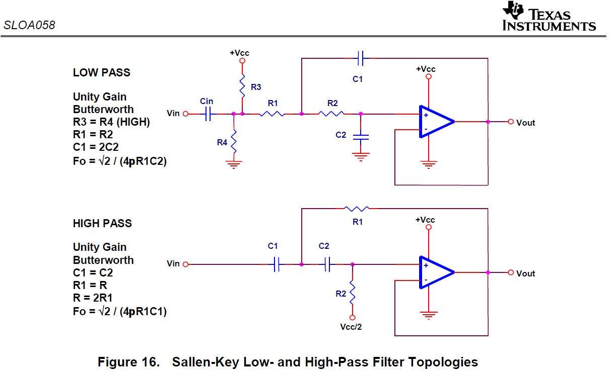
TI tech note.JPG

If you compare the the schematic I ripped off from fDeck you can see that it's pretty much a straight forward implementation of these filters. With the HPF section it's two of them in series plus the extra 'resonating 133k resistor'. Now, when I added my own LPF filter I didn't consider a couple of things and this will impact the filter response. First TI suggests that the filter wants to see a high resistance for R3/4 before the filter and I don't know if I have that as I simply took the output of the buffer and went straight into the filter. When I put this filter into the on-board pre-amp design I'm working on I'll experiment with the pre-filter resistors more carefully as it may impact response and/or stability. Second (and more relevant here), I failed to notice that "C1=2C2" as it is "C1=C2" for the HPF and, well, I just did C1=C2 cause I'm a noob at this and wasn't paying attention.

Before we see the impact of this 'mistake' in my circuit, a quick side note on plots and comparing because I'm referencing the Broughton plot vs my plot a lot in this (long, I know) post.
the scale of his graph is skewed
This is true and if we don't have the same plot parameters then it's hard to compare. the db/octave cut of 12 db/octave is really only obtained in the linear portion that is deep into the cut. In the more practical region of 15 to 25db cut the slope isn't that steep and it actually changes slightly as the frequency is reduced. Looking at just the low pass filter, if I do a crude measurement of the slope from the plots at around -15 db cut I get the following table that indicates that both devices have similar performance (including the apparent increasing slope as freq shifts lower):
slope compare.JPG

So what I'm seeing is that the overall response of the LPF filter is similar in terms of cut once the filter starts to dig in, but qualitatively I think the 'knee' or Q is different and this impacts the response at the corner frequency for both the HPF and LPF. It was your question about the difference in slope that actually got me to look at the filter response at the 'corner' more carefully for both HPF and LPF. We already saw why the HPF corner looks different, but with the LPF the slightly different response turns out to be a direct result of the values I chose for C1 and C2.
Take a look specifically at the purple traces in the Broughton plot vs my plot. In the Broughton the bandpass is very symmetrical while in my plot the purple trace in particular is noticeably non-symmetric where the pots are set with no bass cut and full treble cut. The HPF has the corner resonance that is (purposely) different from the Broughton, but the LPF looks different too - the corner is 'softer' or more rounded compared to the Broughton. This is because I chose C1=C2 whereas Broughton probably used the proper C1=2C2 implementation. If you plug in values and calculate the response then it all starts to make sense (and shows us how the response can be tuned to our liking): Top is standard implementation C1=2C2, middle is mine at 1:1, bottom is even rounder at 1:3
2nd order LPF calc.JPG

The only difference in the three calculations is the ratio of the C1 and C2 capacitors. Top one is with the textbook C1=2C2 ratio and we see the sharper corner like in the Broughton response. This is what everyone expects to see. With my C1=C2, and maybe this is subtle, but I think you can see that the corner is softer or more rounded and matches the response from my plot. If you take this a step further and go 1:3 C1:C2 then the corner really starts rounding off.
Turns out that I'm much more interested in the response with a more rounded corner and so I'm more likely to either keep the current C1=C2 or maybe try to round it off just a bit more. The reason for this, and I've been trying to hide this because, well, this is talkbass... Full disclosure: the reason is because I'm going to use this on a guitar and not a bass. But we can't talk about this stuff on guitar forums as I'm sure you understand. So that's why I'm here. Now, I'm also one of these a on a stand-up bass too, but I've already got fDeck's device for that so my focus here is on how to modify it to suit my dual purposes: on an on-board preamp and as a integrated front end for a tube amp I've built.
The reason I put the LPF in this circuit is to act as an active "tone" control for the guitar. For whatever reason I really do prefer the sound of a LPF over a typical shelving HF filter. It's closer to the response from a standard passive tone control I think. Anyway, when I hooked up this latest prototype I noticed that I liked the response better than if I used, for example, the LPF filter on my Broughton Resonance Filter Equalizer (RFE) set at the "stock corner" shape (Q). I can hear the difference between a sharper corner and a rounder one. My rounder one is smoother and more pleasing to me and I noticed that with the RFE that the more I increased the resonance the less I liked it and the more round I made the resonance the more pleasing it was as a tone control. So what I've done (accidentally) in my circuit is to round it off even more than normal and it makes it sound more like what I want a guitar tone knob to sound like. Probably I'll round it off just a little more though - easy enough because it's just a matter of changing one cap. So my cap ratio mistake was one of those 'happy little accidents' and helped me understand more about how to modify the circuit to get the response I want to hear.
In the end I'm learning to make these circuits from scratch because I'm not able to buy exactly what I want with off the shelf products. I am a high pass/low pass guy. I am not a shelving filter guy. It's a personal preference I guess. But options are limited for HPF/LPF products. Now I'm getting closer to being able to make my own and tune them to get the response I want for the specific application at hand.
 
I have acquired a new and powerful weapon in the fight against unreasonable frequencies....
I have somehow managed to make a working simulation of this circuit in LTspice. I have tried to do this kind of thing once or twice before but could never make it work. But somehow I got all the pieces in place and I can simulate both pots being turned and overlay the calculated frequency response. It actually matches the measurements I made in REW pretty well! Now I can see the resulting frequency response as I make little tweaks to the component values.
Here's the schematic in LTspice LVII:
spice schem1.JPG

And here's the plot:
spicesim3.JPG

This is what I measured (same image as previous post, just again for comparison):
Proto2 response.png
 
  • Like
Reactions: crguti
I'd like to post a correction for anyone who stumbles across this later on. It seems that the order of HPF>LPF vs. LPF>HPF for these two stacked filters has to be looked at more closely. Turns out I have it backwards and the High pass should go first followed by the low pass. The reason is due to placement of a coupling capacitor after the buffer output (which is missing in my previous schematics). There is also the question of whether one is needed between stages or not. In this case because power is a single supply and not a dual +/- then we put a cap at the very end too as it currently has. I found some entertaining reading on this here:
Don't Fear The Filter: Cascading Sallen-Keys
Where it is said that "there is no need for an extra DC-blocking capacitor on the input of this circuit because the highpass already takes care of that. There's also no need for DC-blocking between the stages, because even though the second stage is a lowpass, the signal has already been centered in the middle of the op-amp's response range by the time it gets there."
Here is a schematic of how two stacked HPF/LPF filters should look for both a single supply and dual supply:
stacked filters.JPG

Here is my updated schematic (opps, a mistake - the GND on RV1 in the second part of the HPF should be to Vh or Vref, not ground):
HPFLPFr3.jpg
 
Last edited:
^ how are you controlling the slope of the hpf?
Oh, it's been a while since I was deep diving on this, but I believe the slope is set by the topology, which should be first order if I'm not mistaken. The actual shape of the curve is altered by the resonance tuning of the 133k resistor. I've been using the prototype and it's really working fine and so now I want to make a battery driven version that can go into a guitar electronics cavity.
 
  • Like
Reactions: Jim C and fdeck
i checked your schematics. This is the HPF plot i'm getting in LTSpice:
1760097748204.png

As you can see, the slope is changing as you move the frequency (it was noted before, post #10). This is because you don't have resistors in the inverting side. By doing so you keep the Q constant but also add gain.

A better approach is to get something like this instead, where you get the same slope as you move the frequency. But if it's working and you like it, then go ahead.
1760097886676.png
 
Last edited:
Thanks so much for doing that analysis. Which resistors did you change to get the difference in response? I think overall which is better is a matter of taste, but it might be interesting to listen to some options to find out what sounds best.

Great News! I managed to design a PCB for this project yesterday and I sent it off to OSH Park to have some made! It's my first ever PCB so it's crude, and I'll be lucky if it actually works on my first try. It was only $10 to get 3 made. I'll report back in a couple weeks with the results.

PCB.pngCapture2.JPG
 
  • Like
Reactions: crguti and leonard

Latest posts