• TalkBass has been independent since 1998. Add your voice.
    Create a free account to reply to discussions, view embedded media, and browse with fewer display ads.
    Join freeLog in
    Want zero display ads or expanded classifieds tools? Compare plans.

Modded Behringer Powerplay IEM (build report, DIY)

Thanks, I'll be happy to help if I can!

I don't know if this is the right solution for stereo, in my experience the term "monitor feed" implies a balanced mono signal over an XLR cable. Everything is simpler this way, as a stereo signal comes with some tradeoffs. You either have to run unbalanced signals, which can be problematic (crosstalk and other interference), or you have to run two separate balanced signals which means more cable to manage (and you'd be hogging two channels on the monitor mixer).

Fredde, thanks alot for this!
I was just looking for about the same solution and this fits my needs!

Though, I don't need the 'Bass to IEM' - signal but I would like a stereo feed for my headphones.
Since my requirements are a tiny bit different I have a question about crosstalk.

I did some testing to figure out how signals behave in cables and this is what I found:
- Shared grounding in a single XLR cable gives huges crosstalk (Pin 1: Ground, Pin 2: Bass, Pin 3: IEM Mono)
By "shared grounding", do you mean they share the same shield? Crosstalk in this scenario indeed comes from the pin-2 and pin-3 conductors being close together inside the same shield. (Shared ground implies connected to the same ground rail, which everything should be at some point. How these connections are made is also an important matter, but it has to do with avoiding ground loops, not crosstalk)

- A dual mono jack cable gives no crosstalk, but still gives a mono IEM signal. Each conducer is shielded, which in turn works amazing! (A solution might be to use dual-XLR cables, but now I'm curious as to how cabeling/grounding/buffering affects crosstalk)
You could maybe use one half of the dual xlr for the stereo signal, a bit of crosstalk between right and left might not be that big of a problem. Then use the other half for the bass signal.
This leads me to the following questions:
I can see you're using the balanced Right signal for the IEM which makes it possible not to share the Ground for both bass ánd IEM. Did you do this to reduce crosstalk, or just because it was easier?
I'm not sure I understand the question, could you be more specific?

Will it be possible to use the 5 wire cable in the following configuration without crosstalk?
1: Bass signal
2: Bass ground
3: IEM Left signal
4: IEM Right signal
5: IEM ground
This would depend on the cable. Again, "ground" and "shield" carry different meanings, you would gain nothing by using separate pins for bass ground and IEM ground. Sure, you can use separate shields for them (if the cable has them), but both shields should be connected to the same ground pin.

How about power, will you use a separate cable for that?
And what can I to reduce crosstalk if there is any? How much will buffering the Bass signal help?
Buffering the bass signal will make that signal less susceptible to crosstalk, but it can still induce crosstalk into other signals, especially if these are unbalanced.

The idea in my setup is that the IEM signal is protected by being balanced, while the bass signal is protected by being buffered. This is not a foolproof solution, but an acceptable compromise. I have about 4 meters (12 ft) of cable, and crosstalk is negligible.

The greatest challenge is finding a cable that does the job without being too thick or stiff. If stiffness is not a problem, a Cat7 network cable might be a good solution. It has four individually shielded twisted pairs, so you could use one pair for R, one for L, one for bass and one for power (shield for ground, of course). You could even connect one half of each unbalanced signal pair to ground (at one end only!) to improve shielding even more (for power, I'd use both conductors to reduce voltage drop).
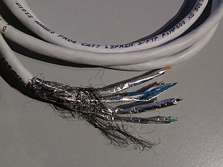
320px-Cat7.jpg


I actually gave this solution some serious thought, but for me, the stiffness (and ugliness) of a Cat7 was too much of an issue. I haven't tested this, so I can't promise crosstalk won't still be a problem.

The simplest solution: Use the belt pack as is (with a battery, no mods), then get the stereo feed from a dual XLR and run a separate guitar cable for the bass signal. Or solder a custom cable with split connectors for this.
 
Thanks, I'll be happy to help if I can!

I don't know if this is the right solution for stereo, in my experience the term "monitor feed" implies a balanced mono signal over an XLR cable. Everything is simpler this way, as a stereo signal comes with some tradeoffs. You either have to run unbalanced signals, which can be problematic (crosstalk and other interference), or you have to run two separate balanced signals which means more cable to manage (and you'd be hogging two channels on the monitor mixer).

Seems reasonable! The benefits of stereo live on stage are minimal aswell..

By "shared grounding", do you mean they share the same shield? Crosstalk in this scenario indeed comes from the pin-2 and pin-3 conductors being close together inside the same shield. (Shared ground implies connected to the same ground rail, which everything should be at some point. How these connections are made is also an important matter, but it has to do with avoiding ground loops, not crosstalk)
You could maybe use one half of the dual xlr for the stereo signal, a bit of crosstalk between right and left might not be that big of a problem. Then use the other half for the bass signal.

I do indeed mean that they share the same shield. Thanks for clarifying the difference between shield and ground and why the problem here is the conductors being close togther inside the same shield. The dual XLR might be something worth the try!

I'm not sure I understand the question, could you be more specific?

Sure, but you already answerd the question. As I understand, balanced signals do no require a ground as a reference. This means that the balanced signal you use for your IEM does not 'share' the ground with the bass signal. (Obviously, by what you explained earlier the sharing doesnt matter, its the conductors inside the shield that were the problem..) Now I also understand that the balanced signal is a way to make the signal less susceptible to crosstalk. So the reason you used the balanced IEM signal is A) because its commonly used, and B) less susceptible to crosstalk.

How about power, will you use a separate cable for that?

Since I dont need the splitter to IEM board I can use the battery space to actually use a battery. ;)
New solution is to use one of the "ground" pins for +9V..

Buffering the bass signal will make that signal less susceptible to crosstalk, but it can still induce crosstalk into other signals, especially if these are unbalanced.

Combining all of the information above I think the best solution for Stereo sound in combination with bass signal is to use a dual XLR cable and solder a 5pin XLR to each end. 9V can either come from the pedal board or the battery.
The reason I want stereo is because I want to use this pack for recording aswell, where it would be nice to have the option for stereo. Next to that, its a fun challange!
 
So the reason you used the balanced IEM signal is A) because its commonly used, and B) less susceptible to crosstalk.
Precisely.

Since I dont need the splitter to IEM board I can use the battery space to actually use a battery. ;)
New solution is to use one of the "ground" pins for +9V..
That works, just make sure the power conductor is short and/or thick enough not to result in too big a voltage drop. But something like 24 AWG should be enough if the cable isn't extremely long (which you don't want in any case because of crosstalk).

Combining all of the information above I think the best solution for Stereo sound in combination with bass signal is to use a dual XLR cable and solder a 5pin XLR to each end. 9V can either come from the pedal board or the battery.
The reason I want stereo is because I want to use this pack for recording aswell, where it would be nice to have the option for stereo. Next to that, its a fun challange!
For recording, I wouldn't recommend routing the monitor signal in the same cable as the bass signal. There will always be some crosstalk, so you will end up with a (faint, but still) trace of the monitor signal on the recorded track. But you can of course connect the bass separately when recording and just use the belt pack as a headphone amp.

Good luck experimenting, please report back how it worked out!
 
For recording, I wouldn't recommend routing the monitor signal in the same cable as the bass signal. There will always be some crosstalk, so you will end up with a (faint, but still) trace of the monitor signal on the recorded track. But you can of course connect the bass separately when recording and just use the belt pack as a headphone amp.

Good luck experimenting, please report back how it worked out!

Indeed, for recording I wouldn't use the bass signal via the cable, only the belt pack as headphone amp.

I finally had some time to test one thing and another. I used a 4 meter (13 ft) 4 wire + shield cable, bass signal was wire + shield, stereo headphone signal was 3 wires. The bass jack directly from bass, via the cable to an interface and the headphone wires of the cable plugged into a little headphone amp I've built (CMoy). Tuned the gain so I had normal levels coming in and oud, stopped playing the bass, played some music to the headphones and recorded the crosstalk on the bass channel. This way I could really see the difference. (The image shows 3 different recordings. The clips are gained a sick amount, and zoomed in upon to make the noise visible.)

The first track shows an amount of crosstalk which would be audible via the bass amp, so not a good solution.

Next I tried buffering the bass signal and recorded the same part. Input signal of the bass set to nearly the same levels. As you can see the crosstalk disappeared! The dots you see is a little hiss, so low you wouldn't hear it.

To check out my weird theory on 'shared ground' I connected the GND of the headphone signal to the shield of the cable and ran another test. The freed wire could be used as a power supply, but I haven't tested that. As you can see the crosstalk is negligible as well, if any it might be better.

Summary of the test:
It's possible to use a 5-pin XLR (DMX for instance) and get a stereo IEM signal.
The bass signal needs to be buffered to remove crosstalk.

Hopefully this helps any of the future builds!

If I built this, obviously, results will be reported back!
Thanks for the help
Schermafdruk 2017-02-25 17.50.06.png
 
It seems i cannot edit the original post anymore, but here's a new version of the schematic.

CHANGES:
- Fix typo in pin numbering
- Optional socket for gain resistor. This makes it easier to change the overall gain if needed.
- Trace cuts have changed in the new version of DIYLC, and not for the better IMO. I've added a legend to help identify them.


monitor_mixer_behringer-FINAL-2018-03-12.png
 
Last edited:
Hi guys
1. What is the best 5 pin lead to run it from the P1 5pin xlr to the pedal?
2. Is no1 connector from combo xlr on connector board (top left) soldered to GND 1 at 5pin xlr bottom left?

Looks like it is. Just want to confirm.

I'm a newbie.

Thx.

Marcin
 
Where do I place my order?
Such a tool is needed for all of us. I prefer stereo IEM and blend mono bass to both ears as the stereo blend allows for better separation/definition IMO. For me just the straight bass signal is fine without all the tones from my pedal board as my biggest issue is the quality of gain structure I get back from the house. I don't need to hear how cool my xyz pedal sounds just that I'm playing the right part.
 
  • Like
Reactions: Steve Hamilton
Where do I place my order?
Such a tool is needed for all of us. I prefer stereo IEM and blend mono bass to both ears as the stereo blend allows for better separation/definition IMO. For me just the straight bass signal is fine without all the tones from my pedal board as my biggest issue is the quality of gain structure I get back from the house. I don't need to hear how cool my xyz pedal sounds just that I'm playing the right part.

Well, you seem to have exactly the right preferences ;)
 
Where do I place my order?
Such a tool is needed for all of us. I prefer stereo IEM and blend mono bass to both ears as the stereo blend allows for better separation/definition IMO. For me just the straight bass signal is fine without all the tones from my pedal board as my biggest issue is the quality of gain structure I get back from the house. I don't need to hear how cool my xyz pedal sounds just that I'm playing the right part.

I'd be happy to make a board for you! We just have to work out what you'd exactly want. Hit me up if you're interested.

So, a while ago I built the device without the direct send and it works great! Below are some pictures :D
Sadly, I have a loud (I mean ear deafening) pop when I power-on the thing. I disconnected my board and reconnected the old XLR board, but the loud pop remained. Even without any board connected nothing changed. I tried capacitors on various places, like parallel to the power-switch, and resistors from 9V-0V on various places. Nothing made the loud pop disappear.

Now I wonder if anyone else has the same problem? Did I somehow damage my P1, or is this a design flaw in the original P1? Next to that, can anyone help me out and try to find the problem and fix it. Please share your thoughts.

2017-10-28 16.38.36.jpg
2017-10-28 16.38.17.jpg
2017-10-25 15.28.51.jpg
2017-10-28 16.41.06.jpg
2017-10-28 16.43.48.jpg
 
I'd be happy to make a board for you! We just have to work out what you'd exactly want. Hit me up if you're interested.

So, a while ago I built the device without the direct send and it works great! Below are some pictures :D
So you etched a board for this, cool! Are you planning on making a commercial product out of it, or are you in the business of etching boards? Would you mind sharing your schematic (with your changes) in this thread?

Sadly, I have a loud (I mean ear deafening) pop when I power-on the thing. I disconnected my board and reconnected the old XLR board, but the loud pop remained.
I think my unit pops a little, but not anywhere near ear-deafening. Maybe you have a bad unit? This is a usual problem with op-amp designs, they are unstable during the few milliseconds it takes to power up. There really isn't any really simple solution, you have to make a soft start circuit that opens the signal line after the amp is powered. (There is a reason most all effect pedals are powered on when you plug in the jack and not when you switch on the effect.)

Of course, it could be something else, like some capacitor gets discharged when you flip the switch, poor output coupling or something. Do you have the 1M bleeder resistor across the output (the one in orange in my latest schematic)?
 
So you etched a board for this, cool! Are you planning on making a commercial product out of it, or are you in the business of etching boards? Would you mind sharing your schematic (with your changes) in this thread?

Sure, pictures below! I made some changes after I made this, because I switched the left and right channel, and I made some improvements. I'm not planning to make a commercial product out of it and I'm not in the business of etching. Its just a hobby and these days its so cheap to get a prototype etched I figured "why not". The results and possibilities with etching are amazing! :D

I think my unit pops a little, but not anywhere near ear-deafening. Maybe you have a bad unit? This is a usual problem with op-amp designs, they are unstable during the few milliseconds it takes to power up. There really isn't any really simple solution, you have to make a soft start circuit that opens the signal line after the amp is powered. (There is a reason most all effect pedals are powered on when you plug in the jack and not when you switch on the effect.)

Of course, it could be something else, like some capacitor gets discharged when you flip the switch, poor output coupling or something. Do you have the 1M bleeder resistor across the output (the one in orange in my latest schematic)?

My guess is the unstable op-amps on power up. I dont think its a capacitor because its a to sudden pop, capacitors tend to sound more like a 'whop' in stead of 'pop'. The 1M bleeder resistor might help, but thats on the output circuit of the 'new' board, and the problem remains regardless of the board.

For now I can just power on the device and then plug the headphones in.
Schermafdruk 2018-04-03 10.06.01.png
Schermafdruk 2018-04-03 10.04.49.png
 
Cool, I've thought about sending my designs for etching many times, but never gotten around to it.

The schematic looks ok to me, also the unused half of the op-amp seems to be properly terminated. I would maybe add decoupling caps for the power rails, but I'm not sure it would help this particular problem. You have a socket for the op-amp, right, why not test with some other model and see if it behaves differently? The NE5532 you have there should is a good choice, but who knows.

However, if this problem indeed persists when you convert the unit back to stock, I'm not sure there's anything you can do. The problem would have to be in the Behringer board.
 
I'm pretty sure the problem is in the Behringer board, thank for your thoughts though!
Decoupling caps might help the bass signal, which value would you suggest? Couple of pFs right?

I've sent my designs to Seeed studio. Their PCB printing service is called Fusion. Its not the highest quality but it beats the hell out of every DIY test board. If you want me to convert a schematic to layout I'd be happy to! Just PM me.
 
I thought I should post this as well, it's another mod for the Behringer P1. I usually keep the unit on my bass strap, and the stock belt clip makes it very top heavy. After having it fall off a couple of times, I grew annoyed enough to design a better one. So if you own, or have access to a 3D printer, go ahead and print it!

Check out the design on Thingiverse: Better Belt Clip for Behringer Powerplay P1 In-Ear Monitor by SubSite

2017-11-16 00.23.22.jpg
 
If anyone wondered if Fredde's design would fit onthe single XLR connector board, here's the answer: it fits!
Schermafdruk 2018-04-06 15.47.29.pngSchermafdruk 2018-04-06 15.47.02.png

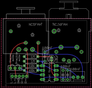
This way you would free up the space for a battery. Not that that would be very useful because the connector board is not powered by the battery. So I took the liberty to change some things in Fredde's design and merged it with my own. I ditched the low-cut filter, because I think you won't want it. I added a power socket which connects the 9V power supply to the battery connector of the Behringer board and receives back +9V and -9V from the Behringer board. Next to that I added a jumper to make it possible to use this design as in practice mode (bass is sent to the left channel of the P1) or in stereo mode (the left channel from the XLR-5 is sent to the left channel of the P1).
Schermafdruk 2018-04-09 15.33.11.png Schermafdruk 2018-04-08 12.23.47.png

If there are any questions, let me know!
 
After some experiments I ran into the question "Why cant the P1 (in my design from April 9th) be used as a stereo Practice amp?" and so I did some test!
2018-06-26 18.47.45.jpg
I've disconnected the connector board and built the schematic as shown beneath. Basically the buffered bass is passively mixed with the headphone L and R signals and then sent to the Behringer P1 via the white terminal.
This passive mixing only works when the headphone signals are of low impedance. (This is why the bass has to be buffered first)
Schermafdruk 2018-06-26 22.15.18.png
Now I'm wondering how I can calculate/determine the best values of the mixing resistors, R3, R5, R6 and R10. I'm also wondering why it doesn't matter if I connect to the + or the - side of one of the channels. Of course the polarity is switched, but other than that I didn't hear any difference.

Can anyone help me out?

Later on I'll make an board design :D