
• TalkBass has been independent since 1998. Add your voice.
    Create a free account to reply to discussions, view embedded media, and browse with fewer display ads.
    Join freeLog in
    Want zero display ads or expanded classifieds tools? Compare plans.

My "super SVT" and a polarity switch question...

So I finally got my "super SVT" working last night. I'm stoked!

This little project has been years in the making. I bought the thing in pieces off ebay many moons ago. Got it cheap and found out the power transformer was blown. I had it rewound by Heyboer and requested that it be "beefed up" for more plate and screen voltage. I added lots more plate and screen capacitance as well. I know many people would scoff at this, and modding a vintage SVT is probably generally frowned upon. But I have drilled ZERO holes anywhere, and with a new PT and some new caps it could easily be put back to stock.

Besides, I already have two other 100% stock (other than recapping) early 70's SVT's.

Juiced up power supply:
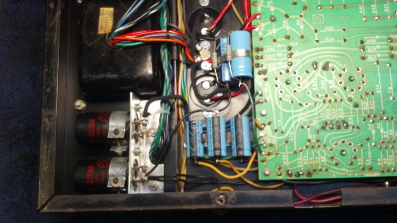
IMG_20140407_234306_198_zpslxmfnc0a.jpg


It's got about 760V on the plates and the screen supply is sitting at around 425V. I increased a couple of resistor values here and there so that the preamp and the driver section aren't getting "over juiced".

I "finished" it years ago, but bringing it up on the variac with all tubes installed would cause it to draw mad current WAY before I hit 120V. I knew a lot less than I do now, and being nervous about either having the thing blow up in my face or kill me, I shelved it. Pulled it back out about a week ago and started poking around. Turns out that when Heyboer rewound the PT they must have skimped on the bias supply, and the power tubes were having a fit because of it. It was only making about -105V vs. -150V. I tweaked a couple of resistor values in the bias network to get it back into a useable range, and voila! It's alive!

Running on old but still working set of Sovtek KT88's and slowly increasing the bias settings, I was running it into my scope and 4 ohm dummy load. All was well and looking good until I was running it hard and "POP"! I shut it down immediately and noticed a wisp or two of the magic smoke escape from the preamp. Pulled it apart and found this:

IMG_20140418_183504_641_zpsjkbzi2rt.jpg


The cap that supplies the polarity switch exploded. See the roll of foil? That's supposed to be on the INSIDE of the cap. So... I've never really understood how the polarity switch circuit works or what it does. Can someone explain? I get what it does in something like a B-15, but in an SVT it's totally different. Also, the skit calls for two .047uF 600V caps in series (C24/C25), and it looks like mine only has one? What's up with that? I might pull the pre out of one of my other ones for comparison.
 
Last edited:

There is a diagram here (http://wiki.talkbass.com/index.php?...ath_cap.2C_and_the_three-conductor_power_cord) that shows how it should be wired. The polarity switch connects a chassis grounded 0.047uF cap to either the power line hot or neutral wires. For the polarity wiring, the best thing to do is to look at the amp and see how they wired it. Different pins in the molex connector might be used. It comes down to the circuit above though.

A polarity switch can still be a useful thing to have, even if the amp has a three-conductor power cord. It serves to reduce high frequency noise that may be on the power line from getting into the amp. They specify a 600V capacitor, two 300V caps in series gives you a 600V capacity. All the amps that I see have a single 600V cap.

Manufacturers that keep the polarity switch and have a three-conductor power cord, such as Loud in their current SVT, will use a three position polarity switch. The center position, is the cap disconnected from both the hot and neutral lines. The same as if you removed the cap from the circuit and just had the three-conductor power cord. A lot of people wire their amps this way.
 
Last edited:
Thanks, David. I see why I was so confused now... I must have been looking at either the wrong power amp skit or the wrong preamp skit, because the molex connector connections don't match up between the two. Looking at a matching set now, and I see how things are supposed to work.

I installed a 600V .047uF orange drop and things seem to be working fine. I noticed some pretty high level noise on the scope right as the old cap blew and before I could shut it down last night. That had me nervous that other things might have blown, but it must have been the cap foil contacting some stuff inside the preamp, because all seems to be good so far. I want to test the tubes that are in there now with my bias probe to see how close they are, and if they're ok then I'll give this thing a thorough bench workout.

What do you think I should bias it at since the plate and screen voltages have been increased? Right now it's running at .065V per side, but I wonder if that might even be a bit much...

PS - Blown caps smell AWFUL.
 
As you know, Ampeg's approach is to set the cathode current (plate and screen) to 24mA per tube with the plate and screen voltages shown on the schematic.

Since the bias is roughly set now, I would put the amp on a dummy load, inject a 1KHz sine wave, and look at the output across the dummy load with a scope. At 300W and a 4Ω load the output voltage should be the square root of 300 X 4 or 34.6V. Adjust the bias to get at least 34.6V with no flattening of the sine wave. Repeat at different frequencies, people typically use 100Hz and 40Hz, and find the best bias setting that works across the range of frequencies. You want to ensure that the tube is operating within spec and it sounds optimal. For a 6550A, the maximum plate dissipation is 42W. For push-pull class AB operation and 70% plate dissipation, the bias must not be adjusted to exceed a plate current of (0.7 X 42/plate voltage). Plate current is the cathode current minus the screen current. Screen current is the voltage across the screen resistor divided by the resistor value. If you want a more conservative setting, assume plate current equals cathode current.
 
On board with everything you just said, it's all "old hat" for me...

How did ampeg come up with 24mA per tube, anyway? If you assume the plate voltage is 660V, the bias should be 44.5mA per tube assuming 70% of 42mA for a 6550. I've always assumed the driver tubes had something to do with it.

Running it pretty cold last night (about 62mV per side) as I was unsure of how matched the tubes were. Stuck my bias probe on each tube and got the following readings - 14.2, 18.6, 26.8, 19.1, 20.8, 20.3. Looks like I'll be ordering a new set for this dude, I don't like the matchup between tubes 1 and 3. Any suggestions? I'm leaning toward KT88's due to the higher voltages...

The output looks pretty good with 40Hz and 400Hz inputs, maybe a bit of crossover distortion.
Here was what my bench looked like as of about 3am this morning... you can see my massive 1200W dummy load over there in front of the scope.

IMG_20140419_243734_912_zps1omdlrhf.jpg
 
How did ampeg come up with 24mA per tube, anyway? If you assume the plate voltage is 660V, the bias should be 44.5mA per tube assuming 70% of 42mA for a 6550. I've always assumed the driver tubes had something to do with it.

Running it pretty cold last night (about 62mV per side) as I was unsure of how matched the tubes were. Stuck my bias probe on each tube and got the following readings - 14.2, 18.6, 26.8, 19.1, 20.8, 20.3. Looks like I'll be ordering a new set for this dude, I don't like the matchup between tubes 1 and 3. Any suggestions? I'm leaning toward KT88's due to the higher voltages...

That sure is a nice hideout. Every kids dream, a fridge and a TV beside the desk.

Concerning the sets of tubes, (14.2+18.6+26.8)/3=19.9 and (19.1+20.8+20.3)/3= 20.1 Each triplet is matched pretty well. In the first set the tube pulling 26.8 is going to be running harder so it will wear out quicker and come down. It is clearly better if all tubes are pulling the same current. But a crummy tube seller will match a set like yours together and call it a matched set. There is matching and then there is matching.

Why 24mA.? I can guess. If one tube died and you ran the amp with only two tubes, with the bias set at 72mA or 36mA per tube, the other two tubes would still be below the safe plate dissipation of 42W and wouldn't burn up. It would be interesting to hear Bill Hughes' take on this.
 
That sure is a nice hideout. Every kids dream, a fridge and a TV beside the desk.

Concerning the sets of tubes, (14.2+18.6+26.8)/3=19.9 and (19.1+20.8+20.3)/3= 20.1 Each triplet is matched pretty well. In the first set the tube pulling 26.8 is going to be running harder so it will wear out quicker and come down. It is clearly better if all tubes are pulling the same current. But a crummy tube seller will match a set like yours together and call it a matched set. There is matching and then there is matching.

You should see the rest of my mancave. Tons of tools, MIG welder, compressor, drill press, three large work surfaces and tons of toolboxes and cabinets. I love it!

You think the set I have is close enough? I figured 14.2 and 26.8 would be too far off.

Why 24mA.? I can guess. If one tube died and you ran the amp with only two tubes, with the bias set at 72mA or 36mA per tube, the other two tubes would still be below the safe plate dissipation of 42W and wouldn't burn up. It would be interesting to hear Bill Hughes' take on this.

Man, I never thought of that! I bet you are right. And that means that every single SVT out there that is biased to the factory spec of .072V per side is running cold.
 
Although an orange drop will work, if the cap fails it might short and wouldn't be safe. That is why you will often find a Type Y or Type XY Safety Capacitor used as a line filter. They are designed to fail in a safe way and won't short the line to the chassis.

Absolutely correct. This is for the player's safety as well as everybody around him. X and Y caps have different internal construction that govern the default failure mode. They are also designed for controlled leakage current, standard caps are/do not.

Now it's been a long time since I designed or even analyzed anything with 6550's and KT88's (used to service servo amps with these tubes, servo amps are just limited bandwidth audio amps) but those voltages are IME well beyond what is safe for 6550's, and a bias voltage of -150 volts is a suspect value as it should put the output stage short of class B operation. One of the challenges with running tubes at or beyond the design rating is that things that otherwise might not be an issue can become a big issue. In a push-pull output stage, under clipping (saturation) conditions maximum voltage is impressed across plate pairs. Also, unless the heater is allowed to float (AND the insulating system on the heater windings is rated for at least the same ast the heater to cathode itself), arc over to the heater can occur. In the SVT, IIRC the heater is loosely referenced to ground through the hum balance control, so if the cathode sees more than the V that's the breakdown voltage that the cathode to heater must be capable of. That's somewhere between 200 and 300 volts which may be close with plate voltage of >700V depending on the design of the output transformer's primary. Another place where there can be problems, especially in PCB mounted tube sockets is the pad & trace clearances which must be large enough to prevent arcover even if there is normal contaminants on the surface of the PCB. These are generally set in the design stage and may not be adequate for the increased voltages.

It's a good idea when operating "off sheet" to review all of the fundamental specifications and how the operating amplifier encroaches on them. From that data you will have a better idea where the soft white underbelly of your amp lies.
 
Hey agedhorse, thanks for your comments.

The KT88 datasheet says that the voltages in my amp are well within range. I'm looking at one now, and it lists 800V plate and 600V screen. The voltages on the drivers are also well within spec. I've got a Hiwatt 200 with more voltage on both the plate and screen than this amp, and it's been running fine for years.

The -150V bias voltage I listed is not is not actually at the tube, it's at the bias supply, point D on the schematic.

You do bring up a good point about arcing of PCB traces and whatnot. Time will tell on that one. I don't claim that this amp will work long-term or even short-term. It could blow up tomorrow for all I know. I really just built it as an experiment.
 
You think the set I have is close enough? I figured 14.2 and 26.8 would be too far off.

I've seen worse. When matching tubes, it is equally important to look at the transconductance. The Gm needs to match as well as the cathode current draw. And this matching is best done at the working plate voltage of the amp that the tubes are going into. We don't know how your tubes were matched. I'd want new ones but I wouldn't chuck these ones out.

Although your power supply is overwound, 760V on the plates is about 60V over what is typically seen. Having said that, the max plate voltage of the GE 6550A is specified as 660V in pentode connection. These specs are offered by the manufacturer for an optimal service live. Some tube types can take spec overages, some simply can't and do strange things as agedhorse said.
 
Yeah, I think I'm going to spring for a new set.

The GE6550A might only be rated at 660V, but this amp will be fed nothing but a steady diet of KT88's which typically have higher ratings. The only question is what to get - I'd like to try some from tctubes, but the only KT88's they have are the new gold lions. Bring your wallet!

Actually, they have Sovtek 6550WE's, and that datasheet says 800V max on the plates and 440V on the screens. Those might actually work ok...
 
Have you measured your voltages under high line conditions (120V + 10%)? You may find all your voltages approaching scary levels. Your 760V on the plates will rise by 76 volts to 836V. This is real world.

In pro venues, it's pretty common to see line voltages between 120 and 130V, especially when sourced off of a still, high capacity feeder.

