• TalkBass has been independent since 1998. Add your voice.
    Create a free account to reply to discussions, view embedded media, and browse with fewer display ads.
    Join freeLog in
    Want zero display ads or expanded classifieds tools? Compare plans.

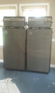
My "super SVT" and a polarity switch question...

The plate voltage for the SVT is 660. I have designed up to 760V with these tubes while with FENDER. The Quiscent current was choses for low dissipation with reasonable distortion. There are many opinions on how to set bias, but the instructions on the chassis are reasonable.
The line cap that failed is available, however a 3 wire cord with green to the chassis is preferred, (leave the cap out).

The SVT will do 300W and new tubes will not get you any more.
Bill
 
Thanks for your comments Bill.

I'll add that some discrepancies arise when discussing SVT voltages because of the different revisions of the amp. The 6146B schematics dated 69 and 70 show the A node power supply voltage as 660V, When the 6550's were used, the A node voltage is shown as 660V initially and 695V later, depending on the schematic revision. These were both with 120VAC 50-60Hz as the specified line voltage.

Interesting to note that the 660V is indicated up to an including Revision D. Rev F and Rev G, indicate 695V, and the later Rev J (1977) is back down to indicate 660V for node A on the schematic. Loud also uses 660V in the modern SVT's. As Bill points out below, they were 660V and the 695V was a schematic error.

I'm fortunate in that where I live, my line voltage is a rock stable 118VAC which is great when using older amps. At some other areas, I've measured as high as 135VAC; 125VAC doesn't seem to be unusual. So for a lot of people, their amps run hotter. Mostly still within their specified operating range. Still, running an am at its upper limit on a regular basis is harder on it.
 
Last edited:
All SVT's through 1977 (my departure) were 660V. What changed was the screen voltage, from 220 to 330 (6146 / 6550). What the schematic says and what is reality is the issue. The 660 / 695 difference was a drafting dept. issue, NEVER HAPPENED!
These amplifiers will easily tolerate 132 VAC. The weak spot is any tube amp is the electrolytic filters and the tube sockets, although neither was ever an issue for the SVT.
The SVT grid bias starts at -150V at power up and settles at a value around -50 hot, if you leave the standby switch always on. The bias is held to cutoff (-150) by the 12BH7 cathode follower driver.

In recent years I have come to believe that running filaments at 6.6 Vs 6.3 results in longer tube life due to a property called cathode stripping.

I learned this many years ago while servicing 50KW transmitters as a side job after I left Magnavox.
 
Last edited:
That's interesting. Some data sheets, as an example, the 6146A (see attached, a lot of neat info packed into it) recommends decreasing the heater voltage to 80% of normal, for maximum reliability, when the tubes are going to be in standby for between fifteen minutes and two hours, beyond that turn off the heater. I've seen facilities reduce the heater voltage on backup radio transmitters.

Heat is always a concern with components in amps such as the electrolytic caps, that operate on the high end of the line voltage operating specification. Also that voltage spike that hits them when the amp is turned on and the caps are discharged. Some cap seem to handle this better long term than others.

My 1971 SVT with original transformers reads 673V at node A with a 117VAC line voltage. When I increase the line voltage to 120VAC, node A reads 690VDC. Some transformers must be overwound. I often read voltages that approach 700V in these amps on that node. Since line voltages are often above 120VAC, voltages in these amps are going to be higher.
 

Attachments

Last edited:
Lower heater voltage is not an issue when there is no cathode current. If the cathode has lower temperature areas, they will strip with cathode current. The DC voltage you observe is dependent on clean sine wave power at the outlet, not always the case. The machines that wind transformers are usually absolutely accurate, if programmed correctly.
 
  • Like
Reactions: AlexanderB
I haven't checked to see what the voltages are in this amp with higher than 120VAC input. I'm not really worried about it, as the line voltage at my house is a stable 120.1VAC and I doubt this amp will ever see a stage.

How awesome is it that I have the man himself, Bill Hughes, posting in my thread! Thanks for your input Bill! I'm curious why you don't think that ~100V more plate and ~75V more screen voltage would produce a little more output, though...
 
  • Like
Reactions: AlexanderB
The form factor (peak to RMS) gets corrupted is the line coming is from the street! The form factor is 1/sqrt(2) for ideal sine wave.

I may have miss-understood...higher plate and screen will make more power...but at the cost of reliability.
 
Hey Bob, I actually did get this thing going a couple years ago. I forgot I even started this thread, haha. Turns out when they rewound the PT they skimped a bit on the bias supply, so even with the bias set all the way negative the thing was going into runaway as soon as I flipped it off of standby. I just had to swap out a few resistors in the supply network to get the range back in spec.

Unfortunately, it doesn't make any more power than a stock one. It sounds a little "stiffer" though, if that makes any sense... either due to the higher voltages or the increased capacitance in the power supply, or a little of both.
 
  • Like
Reactions: AlexanderB