• TalkBass has been independent since 1998. Add your voice.
    Create a free account to reply to discussions, view embedded media, and browse with fewer display ads.
    Join freeLog in
    Want zero display ads or expanded classifieds tools? Compare plans.

Official Ampeg Portaflex Club

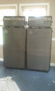
Sure as soon as the wife is back from South America in May, she's the photographer. The 835 is being fixed now, it still worked but had lost a lot of volume, I suspect the coupling caps are shorted, probably also the bias caps, the power tubes were running hot. The power amp kind of looks similar to an old McIntosh it's chrome plated, it has separate pre and power amps like an SVT.


The 835 is a nice amp.

Loss of volume could be as simple as a worn out tube. In an old amp, it isn't unusual to have to change the electrolytic caps including the bias cap on the power tube cathodes. A good cleaning helps. The tube sockets need to have gunk and oxitation removed from the contacts, deoxit works well here. The power resistors need to be checked.

More information in the talkbass portaflex wiki. Follow the links at the top of the page.
 
The 835 is a nice amp.

Loss of volume could be as simple as a worn out tube. In an old amp, it isn't unusual to have to change the electrolytic caps including the bias cap on the power tube cathodes. A good cleaning helps. The tube sockets need to have gunk and oxitation removed from the contacts, deoxit works well here. The power resistors need to be checked.

More information in the talkbass portaflex wiki. Follow the links at the top of the page.

Thanks, yeah I tried new tubes, they guy who has it now used to do Ampeg's warrantee work in Boston during the 70's, he's good.
 
  • Like
Reactions: beans-on-toast
Speaking of bassamps, anyone with one or knowledge of the speaker connections on these want to lend an opinion?

I haven't quite been able to track down the exact model I've got here, it's got a 2x 6SN7 preamp (one in the upper control panel, one below), 6SN7 driver, 2x 6L6 power tubes, 5U4 rectifier, and the OC3 tube. Seems to be an amalgamation of the 835 (5U4/OC3) and 625 amps (6L6) which is making identifying certain parts a huge pain in the backside.

The speaker was disconnected with the leads cut off when I got the amp, which I'm really hoping doesn't mean there was an issue with either the speaker or the OT, but either way it appears the speaker output is an RCA type connector. I've seen some of the 835 schematics showing what could be that kind of connector, but I wanted to see if anyone had any pictures of theirs? I'd like to swap this over to a 1/4" jack but I want to make sure I'm tracing the wiring correctly before I do anything drastic.

Coming out of the secondary side of the OT appears to be three wires, two yellow, one green. Green goes to the ground terminal strip. One yellow wire is connected near the PI so I'm assuming this is a connection for the NFB loop, and the other yellow goes to the RCA connector. The outside of the RCA connector seems like it is just connected through the chassis ground, the pin would be connected to the 8 ohm secondary. There's another bundle of wires popping up from where the OT primary connections pass through but they're wrapped and sealed off.

Here is the OT primary pass through (lower) and secondary (upper). You can see the extra bundle of wires and the wiring for the RCA connector (bottom of the image).

ZNspwSi.jpg


Following what I believe are the ground and NFB connections along the amp a bit you can see where the yellow terminates on the other side of the resistors going to the PI

2yyjwVZ.jpg


And where the green terminates with some wire wound resistors around the power tubes and cap grounds


LJ3M1rc.jpg
 
The 835 schematics show that the OPT transformer is a Stancor A8056 and the PT is a Stancor PC8412. Some had the PC8411. Attached is the Stancor pdf catalog. The index at the front shows what page those transformers are on. The A8056 specs show that the secondary side is 8 and 16 ohms so there are three wires on the secondary.

The problem with some old transformers is that the colors coding on the wires can fade. It isn't unusual to have one wire to the RCA jack and the return on the chassis as you've found.

Note that this amp has a link from the ground bus to the RCA jack. If the yellow is part of the feedback circuit to the PI, it is the 16 ohm tap. Normally you use the highest impedance tap for the feedback. The yellow to the RCA is the 8 ohm tap. Green is return and goes to ground.

I've included some images that will help. 1-5 are high rez so you might not want to use a phone.

Note the same unused wire bundle in both amps.

Stancor PC8411.JPG

1.JPG

2.JPG

3.JPG

4.JPG

5.JPG


Stancor PC8411.JPG
 

Attachments

  • Like
Reactions: coreyfyfe
Thanks for those, definitely helpful. This model has the 8411 or 8412 PT the original labeling is on the side of the transformer but it's down in the workshop for now and I don't recall exactly which. Seems like I have the wiring tracked down right, at least. I need to clean up the top of the chassis, it's very rusted at the moment - part of the reason I want to swap out the RCA connector, it's rusted as well.
 
  • Like
Reactions: beans-on-toast
These old amps can be a rat's nest.

I would isolate, the to be installed ¼" speaker jack from the chassis and connect the ring (speaker return) to where the PI grounds to the ground bus. Also connect the OPT secondary ground near there.

It's one long ground buss similar to what's been posted above, but that's basically the plan.

I realized last night that I couldn't find the bias cap, there's the same big blue wire wound resistor but thinking back I didn't recall a cap. I'll have to confirm but between the 835 and 625 schems something like 250ohm/10W and a 50/50 should be about right? Seems to be what they went with on most of the 6L6GC cathode biased amps. That or 175/10W and similar caps. The two cans were 40/40-450V and a 20/20/20-450V, 100/50V. I had the 40/40 and a 20/20/20 so I swapped those and added a separate 100/100V on the other side. There was a bundled pair of 16uf/600V in the back (yellow guys here), I swapped those for a dual 16uf/500V cap that I had, but have a 30uf/600V on order which is going to take its place. None of the schematics show anything above 500V so I was going to just stick with the 16/16-500 but I have to imagine the 600V was there for a reason and not just because that's all they had in stock so I'm going to go with the 30-600.

f0bpBPV.jpg
 
In older amps you find that sometimes the bias circuit was just a bias resistor. As far as I know the 6 and 8 series amps had a cap and a resistor. The resistor was usually 175 ohms, 10W, the cap was 30uF @50V. Changing these components changes the bias, like changing the resistor in a fixed bias amp. My point is, you can set the bias in a cathode biased amp by changing the components. The bias requirements will change with the plate voltage. If an amp has a lower plate voltage like in this one, the optimal bias will change. Most of their amps used a 250 ohm 10W resistor and a 50uF 50V capacitor, the cathode voltage was 36V DC. The cathode voltage was set in the older amps for 25V DC.

But you really have to measure the cathode current and select values to set the bias optimally. People may find this odd, but I find that listening to the how the amp performs is most important. I set bias roughly, then adjust it by ear, then check if what I picked is within a safe operating range for the power tubes. Depending on the application, running the tubes a little hotter or cooler will make it sound better. Hotter comes at the expense of shorter tube life.

The parallel yellow caps will give you a 32uF @600 capacitor. Smaller in size and less expensive back then than that a single cap would have been.

The high capacitor voltage rating would be used on the first cap in the power supply. When the amp is turned on and the caps are drained, there is a short voltage spike that can exceed 500V DC till the cap charges. The first cap takes the hit while the downstream caps charge. A cap can take more than it's rated DC voltage but it shortens its life. Using a higher voltage rating adds an engineering safety factor and promotes a longer service life for the cap. If the 600 V cap is anywhere else, they were simply using what they had available. BTW, a higher rated cap will last longer, even if it isn't being stressed. The problem with using higher rated caps is that they have a larger footprint so it is hard to fit them in.

If it ever comes up, I have a small circuit board that I use for the first node position in B-15's. It can work in many amps, the cap value can be selected as per the requirements. It uses two caps in connected series and allows for a high voltage rating. Perfect for node A. Much better than the long cardboard tubes that some places sell. The board is here: OSH Park ~ Profile for bax (B-15 A node V1.2D). I really like the Nichicon GW series snap-in caps.
 
  • Like
Reactions: coreyfyfe
In older amps you find that sometimes the bias circuit was just a bias resistor. As far as I know the 6 and 8 series amps had a cap and a resistor. The resistor was usually 175 ohms, 10W, the cap was 30uF @50V. Changing these components changes the bias, like changing the resistor in a fixed bias amp. My point is, you can set the bias in a cathode biased amp by changing the components. The bias requirements will change with the plate voltage. If an amp has a lower plate voltage like in this one, the optimal bias will change. Most of their amps used a 250 ohm 10W resistor and a 50uF 50V capacitor, the cathode voltage was 36V DC. The cathode voltage was set in the older amps for 25V DC.

I really need to sit down and map this amp out. I've been going off of an amalgam of the 625 and 835 schematics in the wiki trying to nail down what should be where but it's really not a perfect match for either with the extra tube in the pre. I've seen the 820, 824, and 825 models listed in the ampeg book but schematics for anything outside of the 625 and 835 are pretty hard to come by. Either way, a good project for the next few months. Hopefully I'll get it up and running at some point and I can get to tweaking the bias around.

Edit - actually now that I'm looking at the schematics in the wiki again, there's one that might be close to what I have here. The first 835 schematic listing (pdf link) shows two 6SL7s and an 6SN7, two EL37, 5U4 and OC3. This amp is only a single input, switch for on/off, and one set of controls, but this schematic lines up the tube complement a little better, especially if someone just substituted the 6L6s (they're newer production) for the EL37s.

Edit again - nevermind, this one shows two 6SL7s before the connector to the lower chassis, mine has one octal up top, two octals down bottom. This is going to drive me nuts.

Also, I'm trying to track down the green wirewound resistor you can see it the images above. Looks like it runs from pin 4 of one of the power tubes to the ground terminal. That I haven't seen on any of the schematics and I'm not sure what it's doing there to be honest.

Another shot of it here

Ij2SAKR.jpg
 
Last edited:
Edit - actually now that I'm looking at the schematics in the wiki again, there's one that might be close to what I have here. The first 835 schematic listing (pdf link) shows two 6SL7s and an 6SN7, two EL37, 5U4 and OC3. This amp is only a single input, switch for on/off, and one set of controls, but this schematic lines up the tube complement a little better, especially if someone just substituted the 6L6s (they're newer production) for the EL37s.


That kind of makes sense. Ampeg used to use the same amp and modify the input. Sometimes there were mic input, others had a variable input impedance so it could be dialed in to match the pickup, some had lots of ¼" input jacks. They customized it based on the customers requirements.

The 0C3 was used in Leslie organ amps like the 147 and others back then. It's an interesting tube. It is a voltage regulator that would drop about 75V. Often it was used to drop the voltage going to small signal tubes. SO those tubes would see a constant DC voltage even when their load changed. They are also used on tube cathodes to maintain a voltage.

BTW, the amp looks like it will clean up pretty well.
 
Last edited:
You are kinda convincing me to but some new latches, where did you bought this one? thanks a lot for the help I really appreciate it.

View attachment 841622

Chris - I use stainless steel latches from SouthCo, part number 97-50-110-12. The round keeper is part number 97-57-105-24. I use #8 x 2" flat head sheet metal screws to attach the keepers to the lid. I purchase the latches and keepers from D.B. Roberts but you can probably find them from other companies too.

Latch.jpg
 
Chris - I use stainless steel latches from SouthCo, part number 97-50-110-12. The round keeper is part number 97-57-105-24. I use #8 x 2" flat head sheet metal screws to attach the keepers to the lid. I purchase the latches and keepers from D.B. Roberts but you can probably find them from other companies too.

View attachment 843561

That sheet metal screw sure looks like it is a lot easier to install straight compared to the vintage type four sided lag bolt.
 
  • Like
Reactions: beans-on-toast
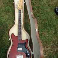
AussieMark, that AEB-1 is sweet! Rick Danko played the hell out of his fretless version.

Say, quick question on recovering the grille cloth for my double baffle B-15N - does the cloth wrap around the edges or is it stapled to the front? I think the former, but hard to tell based on pics.
 
Last edited:
Chris - I use stainless steel latches from SouthCo, part number 97-50-110-12. The round keeper is part number 97-57-105-24. I use #8 x 2" flat head sheet metal screws to attach the keepers to the lid. I purchase the latches and keepers from D.B. Roberts but you can probably find them from other companies too.

View attachment 843561

Mark! Thanks so much! thats going to help a lot since the big screw that comes with those vintage latches its to big for the piece of wood where they attach. Its awesome how all you Portaflex Lovers are willing to help those with little or no experience!
 
AussieMark, that AEB-1 is sweet! Rick Danko played the hell out of his fretless version.

Say, quick question on recovering the grille cloth for my double baffle B-15N - does the cloth wrap around the edges or is it stapled to the front? I think the former, but hard to tell based on pics.

On the double baffle it wraps around. On the single baffle it is stapled to the front.
 
It helps to glue a layer of black fabric store felt to the front surface of the baffle prior to installing the grille cloth. It cushions the cloth, helping keep it tight against the baffle and reduces any flapping. Cut out the felt around the speaker hole.
 
In older amps you find that sometimes the bias circuit was just a bias resistor. As far as I know the 6 and 8 series amps had a cap and a resistor. The resistor was usually 175 ohms, 10W, the cap was 30uF @50V. Changing these components changes the bias, like changing the resistor in a fixed bias amp. My point is, you can set the bias in a cathode biased amp by changing the components. The bias requirements will change with the plate voltage. If an amp has a lower plate voltage like in this one, the optimal bias will change. Most of their amps used a 250 ohm 10W resistor and a 50uF 50V capacitor, the cathode voltage was 36V DC. The cathode voltage was set in the older amps for 25V DC.

Looks like the cap was there, it was the 100uf/50V portion of one of the cans. Hadn't traced out where that cap was connected until now.

The resistor isn't quite reading right but I haven't tried pulling it from the circuit, might give me an actual reading when it's disconnected from the caps and such. Have a 250 ohm resistor in my parts bin but some alternate values on the way so I can optimize a bit once the amp is ready to go.
 
  • Like
Reactions: beans-on-toast
Now I just need to get the cloth on straight!

That takes some practice. Here is my technique.

First cut the cloth to size and carefully inspect it for any flaws. I once installed one that had a tiny knot in one of the fibers. Every time I looked at the grille, my eye was drawn to it. I had to start again.

I lay the cloth down and position the baffle over it. I then clamp the baffle down tightly onto a sheet of plywood, slightly larger than the baffle, so that nothing can move. Pull one edge around and staple it. Then do the opposite edge. Then the other two. The final step is heat shrinking the cloth. To do this I heat the oven, open the door wide and hold the assembly in front of the oven. Move it closer or further to regulate the temperature. Close the oven and let it come back to temperature. Repeat if necessary. I tried a heat gun once and the grille went ping and I was left with a hole in it.

I imagine that in Mexico, you can just leave it out in the sun.
 
  • Like
Reactions: helpcraft

Latest posts