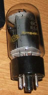
I'm not aware of a pic-by-pic tutorial but if there is one, it would be on
http://www.ampegv4.com.
Not all V4B's can be wired 120 or 240. Some just have a 120V volt winding, some have dual 120/240 volt and can be wired for either voltage. The power transformers all have a pair of red wires and a pair of green wires. The other wires are for the primary windings for the power line input. If your power transformer just has two black wires, it is just a 120V transformer. You would need to replace the transformer or get an external 240 to 120 transformer.
If you see four additional wires (typically black-white stripe, black, blue, blue-white stripe), you can rewire it.
In any event, here is how a tech would do it. Bill is right about having a tech do the work

.
Below are two segments of the 71 V4B schematic. The first is the original, the second highlights the changes that a tech would need to make.
1. There are two power transformer primary (power line side) windings, two wires for each winding. For 120VAC operation, the windings are connected in parallel, for 240VAC operation, they are connected in series. The connections are made on a seven lug terminal strip that is located next to the power transformer. The blue-white wire is currently connected to the black-white wire. Disconnect the blue-white wire and connect it to the black wire. The connection from the black wire to the blue wire needs to be disconnected BUT the blue wire needs to remain connected to the pilot lamp, polarity switch, AC outlet, and line power. How to best do this would depend on how the amp is wired. If you post a pic of the terminal strip, I can tell you the best way to do it.
2. Replace the 10A external fuse with a 5A
3. Replace the 6A internal fuse with a 3A
4. Replace the outlet plug.
5. After the power line conversion is made, the bias of the power tubes should be checked.