• TalkBass has been independent since 1998. Add your voice.
    Create a free account to reply to discussions, view embedded media, and browse with fewer display ads.
    Join freeLog in
    Want zero display ads or expanded classifieds tools? Compare plans.

Sanding relief

MPU

Sep 21, 2004
3,703
10,692
56
Valkeala Finland
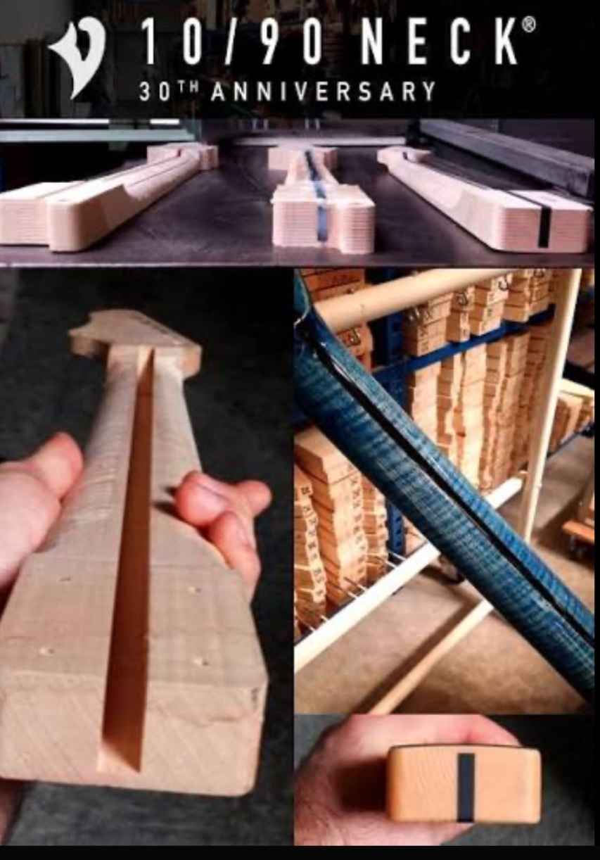
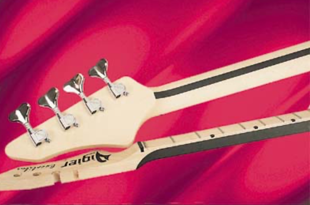
I’m planning to make a neck without a truss rod, like Vigier 90/10 where instead of an adjustable truss rod there’s a carbon fiber beam that makes the truss rod unnecessary. I don’t need reasons why I need a truss rod, I’m looking for advice on sanding relief and leveling the reliefed frets. My plan is to make the neck so stiff that it does not move under string tension so clamping back bow while sanding relief is not likely an option. Where should the deepest relief be, what should the side profile of the fretboard be like and how do I ”level” the frets without really leveling them.
IMG_0270.jpeg


IMG_0269.jpeg
 
I’m going to speculate that you will need to solidly mount the end of the neck and overpower the reinforcement to back bow the neck by the same amount of forward bow required and then straighten the fretboard surface. I figure then as the neck is released it will bow forward with the required relief. Also the frets need to be installed and leveled whilst the neck was held in the back bow. I believe you will find you need maximum relief somewhere in the fifth to seventh fret region.
 
Speculating: Arrange your process so the neck gets fretted and leveled, then clamp in relief and put in massive carbon reinforcement? Certainly seems like the arrangement of the illustrated neck would support that approach.

Otherwise I think you'll want a "leveling" process that actually follows the "quarter-ellipse" relief curve Bruce mentions frequently. The CNC Fret-Master® 2025... Or the Relief-Master® "not-straightedge." Ellipse-edge?
 
  • Like
Reactions: Flamingo21
Speculating: Arrange your process so the neck gets fretted and leveled, then clamp in relief and put in massive carbon reinforcement? Certainly seems like the arrangement of the illustrated neck would support that approach.

Otherwise I think you'll want a "leveling" process that actually follows the "quarter-ellipse" relief curve Bruce mentions frequently. The CNC Fret-Master® 2025... Or the Relief-Master® "not-straightedge." Ellipse-edge?
That sounds like a plan. Or how about I make the neck without carbon bar, clamp it to a slight backbow, level the fretboard, fret and level the frets, then release the clamping and glue the carbon bar in. That way there would be no tension in the finished neck.
 
  • Like
Reactions: Lo-E and T_Bone_TL
I’m planning to make a neck without a truss rod, like Vigier 90/10 where instead of an adjustable truss rod there’s a carbon fiber beam that makes the truss rod unnecessary. I don’t need reasons why I need a truss rod, I’m looking for advice on sanding relief and leveling the reliefed frets. My plan is to make the neck so stiff that it does not move under string tension so clamping back bow while sanding relief is not likely an option. Where should the deepest relief be, what should the side profile of the fretboard be like and how do I ”level” the frets without really leveling them.

View attachment 7369467

View attachment 7369468

Hey Marko;

Another interesting project, with its own technical challenges! I like it.

The technique for creating built-in Permanent Relief is easier than you think. Use normal leveling technique, and then screw it up using too much sanding in the middle, creating a dip. Really, I think that's all you have to do. For both the fingerboard surface and the final fret leveling.

For the fingerboard surface, start with your normal process using a router fixture or a radius block. Make it straight and true, checking with a straightedge. Then go at it with a shorter radius block, but only sanding between the 1st and the 14th fret positions. Keep sanding, shortening the length of the stroke until you are only sanding between the 4th and the 7th. Keep checking with the long straightedge, working the dip until you get the relief curve where you want it. Make the whole dip a gentle smooth curve.

Same thing for the frets. Make them level first with the long beam and the Sharpie. Then use a shorter stone or sanding block to create the dip where you want it. The main thing is to blend the shape of the curve, so you don't end up with kinks or high spots.

The ideal shape of the relief curve should be one quarter of an ellipse from the nut/Zero fret to 5th-7th fret, blending to a straight line from the 9th to the heel.
 
  • Like
Reactions: JIO, Lo-E and REV
Thanks Bruce, looks like I was bit overthinking the difficulty of sanding radius. I think there’s not much sanding to get that 0,2mm -0,3mm relief. I should have the carbon fiber beam coming week so I can start making the neck.
 
Thanks Bruce, looks like I was bit overthinking the difficulty of sanding radius. I think there’s not much sanding to get that 0,2mm -0,3mm relief. I should have the carbon fiber beam coming week so I can start making the neck.

Yes, the correct relief is a very small amount. It's easy to accidentally sand in some relief while trying to make it level. So it should be easy to sand it in on purpose! Just keep checking and measuring.
 
  • Like
Reactions: JIO
My Steinberger XP-2 has no trussrod, it's just one solid chunk of carbon fiber and resin, they cast the relief into it, luckily it has never needed adjustment. Relief more of less perfect and stayed that way. I'm not sure that's possible for a wood neck over the long haul, even with a CF spine, but if anybody can pull it off.......
 
I would suggest making the neck as straight as you can and stringing it up to evaluate how much it deflects under load. Then sand in relief as needed. Even a solid CF neck will deflect a little - my Modulus neck has relief, and it is solid CF and very rigid. If you make a stiff neck and only want a tiny bit of relief, the string tension alone may provide it. I’d you are making the bass for yourself, I think you can design the relief you want. However, in my setup and repair work I have found that different players want different amounts of relief, which is why I don’t build without truss rods myself.
 
I would suggest making the neck as straight as you can and stringing it up to evaluate how much it deflects under load. Then sand in relief as needed. Even a solid CF neck will deflect a little - my Modulus neck has relief, and it is solid CF and very rigid. If you make a stiff neck and only want a tiny bit of relief, the string tension alone may provide it. I’d you are making the bass for yourself, I think you can design the relief you want. However, in my setup and repair work I have found that different players want different amounts of relief, which is why I don’t build without truss rods myself.
This makes sense. Yes, I’m making this neck for myself as a sort of an experiment.
 
This makes sense. Yes, I’m making this neck for myself as a sort of an experiment.
After you have everything worked, you can have the carbon fiber rod 3D printed to your finalized relief. It’s not that expensive using online services, you have to provide a stl file. I would recommend Ponoko they have very competitive pricing especially if you buy 5 or more at a time.
 
After you have everything worked, you can have the carbon fiber rod 3D printed to your finalized relief. It’s not that expensive using online services, you have to provide a stl file. I would recommend Ponoko they have very competitive pricing especially if you buy 5 or more at a time.

??? A carbon fiber rod, 3-D Printed? Really? I know they can print "carbon fiber reinforced" parts by mixing chopped carbon fiber particles in with the plastic resin. That improves the strength somewhat, but it isn't anywhere close to what you get with full length carbon fiber TOW bundles extruded in resin under high temperature and pressure. I don't believe they can do that with any 3-D printing process.
 
  • Like
Reactions: gizmos
I also don't believe that 3d- printed cf has nowhere near the strength of an extruded or laminated cf bar. It for sure is stronger than plain printed plastic but that's not even close enough. There's no need for any relief in cf bar, there's fretboard and frets where relief can be sanded.
 
If the relief needed is only 0.2 to 0.3 mm, isn't it possible to make the fretboard completely straight and create relief by varying fret height?

Sure, that will work. You can also do the reverse; Start out cutting more relief into the fingerboard and frets than you think you might need. Then, when it's all together and you're dialing in the setup, you can lower the relief just in grinding the frets.
 
  • Like
Reactions: Flamingo21 and MPU
I started making the neck. After gluing two 6mm x 25mm carbon fiber beams side to side I shaped the end and glued a maple extension to it. This will be the center beam of the neck.

IMG_5952.jpeg


IMG_5953.jpeg


Then I glued this beam between maple strips. After the epoxy had cured I thicknessed the neck blank in a router jig to 21mm thickness. Then I tapered the neck with bandsaw and router. Next I have to fit the neck to the body, drill holes for neck screws and insert the brass blocks in the neck before gluing fretboard.

IMG_5955.jpeg