• TalkBass has been independent since 1998. Add your voice.
    Create a free account to reply to discussions, view embedded media, and browse with fewer display ads.
    Join freeLog in
    Want zero display ads or expanded classifieds tools? Compare plans.

SVT III Pro schematics

I wanted to run the amp for a while to see if the problem with signal drop was solved. At the same time, I wanted to measure the voltage drop across all the source resistors, cold (just curious) then warm (correct procedure), to see if any of them was way out.
Cold (72F):
6.5mv......12.7mv
6.1mv......2.2mv
2.3mv......5.5mv
7.2mv......2.6mv
Average:
5.525mv......5.75mv

Signal drop occurred after maybe 5-10 min... Turning the plate voltage (tube gain) a few degrees CCW and back up to again 10 restored the signal. Now it's been running with 440Hz 1Vp-p sine, master+gain at 9 o'clock for 45 min without drop.
When I replaced C5, I discovered that AX and AU tubes were swapped. I re-seated them in their correct sockets. Could this have contributed to a failure which could explain the signal drop?
I did not replace C3 yet. All resistors you mentioned (R3 - R9, R81) was measured within spec.

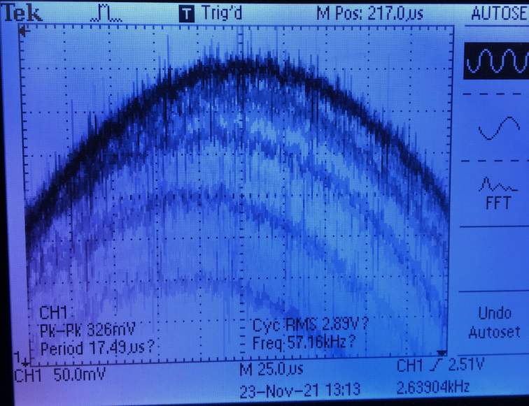
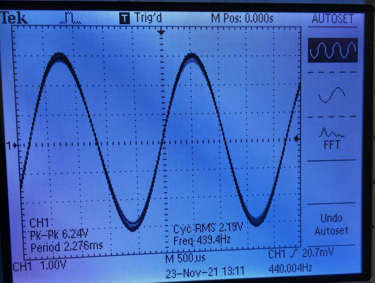
I also discovered that the output amplitude fluctuates a bit, compared to the clean sine input. Master and gain is both at 9 o'clock. See the images. Would this be normal, or do I have even more problems with this amp?
IMG_3584e.jpeg

IMG_3590e.jpeg
 
That’s pretty typical, now measure (the voltage across the source resistors of) the AC current sharing at 1V, 10V and 20Vrms using a 4 ohm load.

This is another way to quantify what is happening during operation.

Yes, swapping the tubes can be problematic. Don’t know if they would correspond to your symptoms though.
 
I have 8 ohm dummy loads. I could parallell two for 4 ohms, or is 8 good enough?

What do you mean by measure current sharing at 1, 10 and 20V?
Do I turn the gain/master until the scope shows 1Vp-p, then measure the same 5W resistors but mVAC? Then adjust gain or master to get 10Vp-p on the scope, and measure?
 
Yes, 2 x 8 ohm loads in parallel will work.

Yes you want to see 1, 10 and 20 volts(RMS, not PP) AC at the speaker output. Measure the same resistors on mV AC. These should be within +/-20% give or take.
 
Yes, 2 x 8 ohm loads in parallel will work.

Yes you want to see 1, 10 and 20 volts(RMS, not PP) AC at the speaker output. Measure the same resistors on mV AC. These should be within +/-20% give or take.

I'm not sure I'm doing it right. The test conditions in the schematics say 1Vp-p sine input, so I used that. I then see only about 100mVAC (I'm using a Fluke 183 True RMS) on the speaker output with master and gain both at 9 o'clock, that's about 3 of 10 on the dials. Am I supposed to turn up gain and/or master until I see 1V, 10V and 20V? That sounds awfully high? Any preference of which of the master or gain to turn up?
Do I need thick cables soldered to the dummy load (they are 8 ohms 100W each)? Now I'm just using thin (22-24awg) with crocodile clips to parallell them, then same type crocs to the oscilloscope/DMM.
Do I measure during normal operation or when signal dies?
Signal restores really easy, just by touching any(?) pin with the multimeter, so that could be difficult. I tried to clip on negative DMM lead to GND leg of R5, signal jumped back to normal.

Sorry for the silly questions, but I really enjoy learning about this.

PS. In the images the oscilloscop was set to 10x probe, but I used 1x. So numbers are one order of magnitude off.
 
Normal operation, what you are looking for is AC current sharing of the output devices. Yes, you are looking at current sharing at the 100 watt level (10V into 4 ohms). For what yo are doing, 22 gauge is fine, croc clips are fine.

I have no idea what else may be wrong.
 
I have 8 ohm dummy loads. I could parallell two for 4 ohms, or is 8 good enough?

What do you mean by measure current sharing at 1, 10 and 20V?
Do I turn the gain/master until the scope shows 1Vp-p, then measure the same 5W resistors but mVAC? Then adjust gain or master to get 10Vp-p on the scope, and measure?
When checking the speaker output, make sure you have the ground lead of the scope connected to the negative speaker terminal. If you connect it to the positive terminal, you'll be effectively shorting the output via the powerline ground.

When testing a bridged output amplifier, you have to isolate the ground.
 
I also discovered that the output amplitude fluctuates a bit, compared to the clean sine input. Master and gain is both at 9 o'clock. See the images. Would this be normal, or do I have even more problems with this amp?View attachment 4481507
View attachment 4481508
If the level is bouncing around, it could be indicative of an intermittent condition- solder joint, loose connector, dirty pots, or intermittent jacks. Try tapping on the pc board and pot cases and watch the scope to see if it's mechanical in nature.
 
  • Like
Reactions: gstaats
Great points. My svt-3 pro had the entire front and back resoldered as the tech had seen several come through with issues like that. It is part of his normal 20+ year old amp servicing. That cleared up an issue on my svt-iii non-pro last year
 
That’s pretty typical, now measure (the voltage across the source resistors of) the AC current sharing at 1V, 10V and 20Vrms using a 4 ohm load.

This is another way to quantify what is happening during operation.

Yes, swapping the tubes can be problematic. Don’t know if they would correspond to your symptoms though.

Do i measure every of the 8 source resistors for each 1/10/20V rms? 24 measurements? Or is hooking into 1 of them sufficient (since I have the "ratios" already) and do the 3 measurements?
Is 1Vp-p to the input a good start? And should I turn gain up to full, then adjust volume to 1/10/20VAC rms on the output? Or do I set gain to e.g. 50%, then adjust volume?
 
Yes, 24 measurements. What you are now measuring is the linearity of the AC current sharing at the various power levels.

The transfer curve Ids versus Vgs varies by device is not linear, this measurement identifies devices that are not sharing proportionally.

This is why there are .47 ohm source resistors at each device. The local feedback provided by the source resistors serve to normalize the current within reason, these measurements verify the effectiveness.
 
I set the signal generator to 1Vp-p sine 400Hz, gain to about 50% (dial pointing at 12 o'clock, anything more and the peak lights up - normal at 1Vp-p signal in?), and then adjusted master until 1, 10 and 20 Vrms on the speaker (4 ohms 200W resistor). mVAC measurements:
1Vrms:
18,02 --- 28,85
17,78 --- 10,29
8,69 --- 17,30
17,45 --- 10,32
10Vrms:
168,84 --- 197,35
169,12 --- 143,51
130,62 --- 177,60
164,90 --- 146,11
20Vrms:
328,37 --- 370,00
328,50 --- 308,20
282,00 --- 351,00
321,00 --- 311,63

Seems at 1V, four are approx. within each others values, three are very low, one is very high.
At 10V, only one is lower than 20% and at 20V they are all within 20%.
 
This is both normal and typical of MOSFET output stages, and why the source resistors are essential to insuring current balance.

The sharing improved with increased current, when it gets worse you have big problems.
 
Just to be on the safe side, I also replaced C4/C28 with CBB2 630V poly propylene film caps (not WIMA MKS 4, I didn't have this type). Also replaced C24/C25 (47uF/100V, better than 35V) and Q1 (TIP50). Was stable for hours. But again, the drop out has been quite random, so I'm not sure.

However, before I gave this back to my father, I decided to measure some test points on the preamp (although this was ruled out as a cause of the dropout since preamp signal was measured fine when the drop out occurred). I just wanted to make sure the preamp also works optimal. The AC is extremely off (some points lacking totally). DC is high, but I guess it's ok(?).

Conditions: 0.2Vp-p sine wave input, 4ohms load. Gain and master @ 0, bass/mid/treble @ 5, line output @ 10 (pot shaft in), pre/post button out.
Should I measure from dirty ground or signal ground?

TP15 (should be 100mVAC, 300VDC): 0-10mVAC. 315.1VDC.
No VAC change with gain change.

TP6 (should be 22VAC, 200VDC): 20mVAC @ 0 gain. 230VDC.
Rises with gain. Ends up at 7VAC with gain to 3 o'clock, at which peak LED lights up so I stopped increasing.

TP7 (should be 700mVAC, 120VDC): 0mVAC@0gain, 260mVAC@3o'clock. 160VDC (at power on, it starts at >200V and drops to 160 and settles).

TP4 (should be 4.5VAC, 0VDC): 2.192VAC. -4.8 to +6.3mVDC.

TP5 (should be 150VAC, 140VDC): 0 to 5VAC. 172VDC (same as above, started on 325, then dropped and settled at 172DC).
Rises with gain. 5VAC with gain @ 3 o'clock, at which peak LED lights up.

After this, I replaced C7 with 47uF/450V and C2/C3/C10 with the same CBB2 630V poly propylene film as above.
No improvements in AC measurements.

I don't have replacements for C25 (330uF/100V) and C19/C200 (22nF/400V), otherwise I would have replaced these too.

Any ideas?
 
Are the cheap Aliexpress CBB22 630V poly propylene film caps a decent replacement for WIMA MKS 4 (400V)?
I've read that poly propylene film caps are superior to metallized polyester (PET) caps (which WIMA MKS is). Is this also true for audio?