• TalkBass has been independent since 1998. Add your voice.
    Create a free account to reply to discussions, view embedded media, and browse with fewer display ads.
    Join freeLog in
    Want zero display ads or expanded classifieds tools? Compare plans.

Two Single Coil PUPs into an EMG Series/Parallel Push/Pull Pot

Bottoms_Up!

For the record, I don't love Raymond.
Apr 14, 2009
1,598
335
63
Worcester, MA
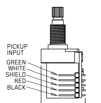
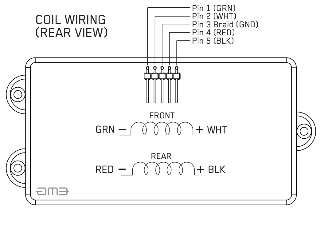
I'm searching for a little guidance. I'm looking to wire two separate single-coil PUPs (and yes, one of the PUPs is reverse wound/reverse polarity [RWRP]) into an EMG series/parallel push/pull pot which has a 5-pin configuration. Looking at the diagrams below, and knowing that both of my PUPs have only the 2 leads (hot and ground), how would the resident wiring gurus here proceed? FYI - I've got the bare wire to EMG solderless pin conversion down to a science

In the first pic (imagining that each coil represents each of my single coil PUPs), I’m assuming green is ground, and white is hot on the top coil. Conversely, I’m assuming black is hot, and red is ground on the bottom coil. What should I do with Pin-3 which is designated as "shield" knowing that my pickups only have 2 leads (hot/ground)? Do I just leave it empty? Add a shield line from the pickup housings? Or am I simply looking at this completely wrong?

I look forward to your replies!

Thanks in advance!
Screenshot 2025-12-30 at 8.08.29 AM.png

Screenshot 2025-12-30 at 8.12.01 AM.png
 
I can’t see your pic (I think there is currently a technical issue with the TB platform). But if you have a multimeter you should be able to figure out which contacts are linked in both switch positions.

Do you have an EMG part number? Is it maybe the push-pull that they use for their TW pickup?
 
Odd, yeah, the pics in the original post showed up ok when you posted it, but a few minutes later, they disappeared.

In any case, I'm not sure we have enough information.
 
So basically, I'm looking to take two 51-P single coils with the typical 2 leads each and wiring them to an EMG series/paralell push/pull pot as a humbucker. I'm using the EMG MM pickup diagram above as an example (as the MM is actually 2 separate coils).

I guess what I'm trying to ask is what goes into Pin-3 (Shield/Ground), if anything, given that the PUPs I want to use each have a ground and lead? Or, am I looking at the (GRN - and RED -) leads on the MM diagram incorrectly? Are they not grounds per se? And if this is the case, how should I interpret the hot and ground leads coming from each of the single coils I've purchased in relation to the EMG wiring diagrams above?

Hope I'm not being too much of a PitA here! And if you're wondering why am I trying to fit a round peg into a square hole, it's just a stubborn design thing. I thought they'd look cool/unique on the headless project I've been working on.

Viola.jpg
Screenshot 2026-01-06 at 6.35.47 AM.png
 
  • Like
Reactions: MartinB
Ground the shield pin, but you may not need that, in the EMG it is either an actual metal shield plate inside or the magnets are grounded (shielded).

Wire: Black on your new pups go to + and white to - on the switch (same as white and black on the EMG)