• TalkBass has been independent since 1998. Add your voice.
    Create a free account to reply to discussions, view embedded media, and browse with fewer display ads.
    Join freeLog in
    Want zero display ads or expanded classifieds tools? Compare plans.

What's that under you bench!?

MrArose13

Guest
Commercial User
Aug 15, 2011
571
171
Atlanta Georgia
www.rosebudbasses.com
Disclosures
Owner/Luthier:RoseBud Basses & Guitars LLC
Experimental chambered RS-5.

This bass has been sitting for quite some time, partially because I wasn’t sure how I was going to get the top around the FB, but mostly because there was higher priority work in the shop. During that down time things changed. Now with some new tools in the shop, a new order of operations is possible and this experiment was a perfect guinea pig. So it’s back in construction and I hope to catch it up with the RS-5 in the “What to do when the wood hits the fan” thread and my 2 custom guitars that are nearing finish sanding (finally)


This will be a 34” 5-string, set neck through body. I haven’t done anything like this before so we’ll see how it goes, so far so good.

- The body- northern ash (the heavy stuff) with a walnut top.

- Neck- 5 piece flame maple walnut neck with scarf joint.

- Finger board - Gabon ebony lined fret less finger board with maple and walnut lines. I shy away from ebony these days, but this was a piece that would have been scraped I got from a shop I was helping out at for a time, it was cut to thin for frets.

- Tuners – Gotho H keys chrome w/black buttons

- Bridge – floating wood lam. walnut, maple, ebony. Tight spacing.

- Pickups – well… if anyone knows how to get a three coil humbucker let me know, that’s what I want, otherwise… undecided. This is an experiment so I don’t want to drop a bunch of money on it mind you. I’ve considered getting three single coil Chinese pickups and just chaining them together, or one single and a soap bar/humbucker… but I just don’t know and would love to hear your thoughts.

So here’s some old stock footage. (Some of you may have seen a lot of this already.) Forgive me if it seems jumbled, I tried to pull all the old info together and make it cohesive.
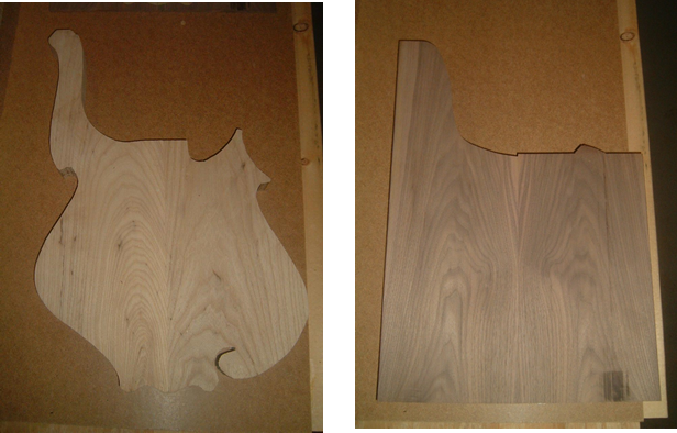
upload_2015-5-16_13-33-56.png


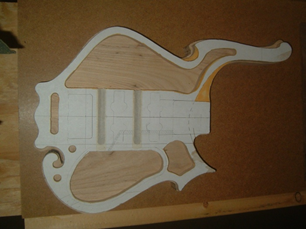
Chamber temp. - this template got changed.
upload_2015-5-16_13-34-54.png


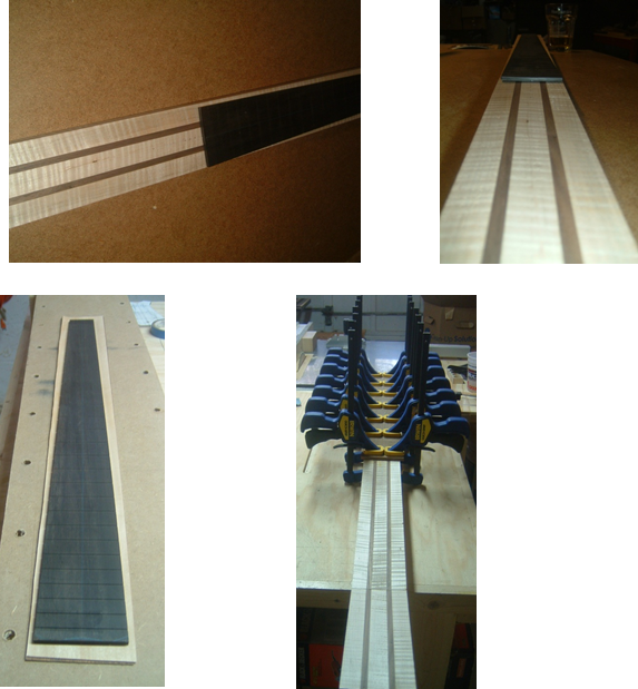
Accent veneer under the finger board glued up as well as the accent veneer under the body end of the neck.
upload_2015-5-16_13-36-11.png


The set neck through pocket is set up and ready to rout.

But wait, there’s more.

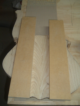
I routed my neck through set neck pocket with a 2 degree pitch (I like having body angle).

To do this, I tapered some MDF by double side taping it to a larger piece of MDF and add a 4/32” shim at one end; I also shimmed the middle to keep the pressure even and ran it through the drum sander. Ripped it in half on the table saw and it look good. Then I clamped the neck to the body lined everything up and double side taped the tapered MDF to the body tight against the neck, triple check my measurements, and then removed the neck. Check the measurements again and (apprehensively) started to rout. I admit, I was so nervous I constantly checked the measurements. In the end it went well enough to consider doing this again.


I took these pic half way through.
upload_2015-5-16_13-40-9.png
upload_2015-5-16_13-40-56.png


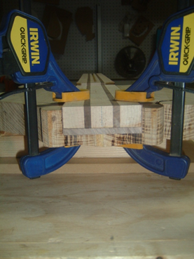
Now to tell you how I did the neck. Well I probably should have told you about the neck first, but… I simply measured my top thickness, (which is just under 1/4") marked it on the side of the neck, and hogged it off with a dado blade on my table saw leaving it slightly proud of final thickness (this gave me my pocket depth by the way). And now I have a nice tight fit and will rout it level once the neck has been glued in. but there is more work to be done before glue.
upload_2015-5-16_13-43-33.png
upload_2015-5-16_13-43-58.png


One more from the back
upload_2015-5-16_13-44-47.png


This is how the bass sat till the beginning of this year.


Full top on a neck through… I searched around and found it very frustrating that there doesn’t seem to be a lot of info out there on the topic, big manufactures don’t even appear to do it either. So I’d like to add my $.02 on this.

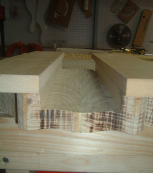
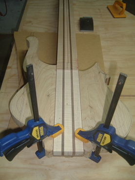
Once the FB was sized and shaped, I then made a MDF template by double side taping the FB to the MDF and running it on the router table with a flush trim bit to get an identical replica. I then carefully added a spline to the underside of the FB template to sit in the TR slot. Next I drilled 2 holes for registration pins through the template and just in to the bottom of the FB. Then I placed the template on the neck blank with the spline in the TR slot and in its proper location and traced around it. At this point, I was able to draw some lines and do some math to determine the waist that need to come off the body end of the neck blank.

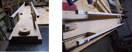
With everything in place, I then marked an angled line (above the FB end) going from the bass side cut away to the treble side cut away. (I’ve got a pic that should help make sense of this toward the end) Now we get a jig involved, this jig lets me clamp the headstock end down and raise a kind of pedestal at the body end to compensate for body angle and route the body angle as if it was a level surface. Maybe that made since… maybe this pic will help?
upload_2015-5-16_13-47-57.png


Thanks to a new shop built tool, I think this jig ^^ may become obsolete.

At any rate, it goes in the jig and I double side tape a stop block on the angled line. With a pattern bit chucked up in the router and the router attached to a sled, I remove the remaining wood. Leaving me with my desired body angle plus a step-down for the top.
 

Attachments

  • upload_2015-5-16_13-32-43.png
    upload_2015-5-16_13-32-43.png
    538.8 KB · Views: 124
upload_2015-5-16_13-52-55.png

Taking the “chunk” out before routing chambers and cavity.

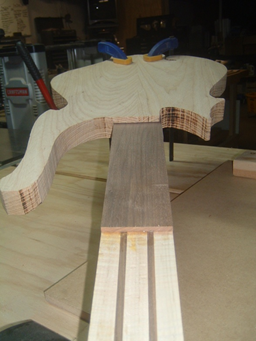
Time for the top. I traced my body template, and cut out most of the cutaways, leaving a tongue section over the neck. A little more measuring and I cut and sand the tongue section angled to match the step. The idea is I only have to make one matching face as appose to 3, more less the complications of curves and it’s under the FB, so as long as the edges are tight it won’t be seen. With things looking good, I drilled for some registration pins and then glue it down.


Now there’s one more part. Due to the body angle, there’s still an air space between the full top and the FB. To address this, I made a small square of the top wood just a little bigger than the overhang of the FB and a bit tall with one straight side. Then glued it down with the straight side butted up against the angled step. Block plane and sand it down to level, No more step. Once again place the FB template in place and route (with a pattern bit) off the extra from the small square.

This works for me, although I think it took me more time to try to explain how I did it than to do it.

upload_2015-5-16_13-55-8.png
upload_2015-5-16_13-55-41.png
upload_2015-5-16_13-57-4.png
upload_2015-5-16_13-57-31.png


Up next is the more recent stuff, I’ll pull that together over the next few days (or week/weeks, so much to do) and pit it out here for you’uns.

Till next time, Happy building. :D
 

Attachments

  • upload_2015-5-16_13-54-31.png
    upload_2015-5-16_13-54-31.png
    840.5 KB · Views: 123
  • upload_2015-5-16_13-56-28.png
    upload_2015-5-16_13-56-28.png
    577.7 KB · Views: 114
The body is absolutely beautiful! I'm concerned about the lower horn though. How does it hit the leg when sitting? Is it comfortable?


Funny you should ask. When I did the prototype of this model the lower horn had more of a hook to it, (as seen in the first pics at the top) and that's just what I discovered. Annoying and uncomfortable... so that got changed quick. Now (like in the last pics) it follows the same line as most lower horns, just chopped short and dished out. you don't even notice it's pointy. Good question, Thanks for taking an interest and checking it out.


Gorgeous.

Thanks man! So far so good.

I hope to get some more on this one up soon, but you know... life and all. :)
 
Maybe a little update on this is in order?


Let’s start with what’s happened in the shop that brought this bass out from under the bench. The only thing more exciting than a new tool, is a new shop made tool… THAT WORKS. I did a search for a jig thread thinking I would tack these on, but couldn’t decide which one to use.

Any who… as some of you have discovered (so did I) it can be a real pain to radius a fingerboard with a sanding block alone. I wanted a radius jig. A whole lot of TB threads and YouTube videos later, I started trying to put something together. A few failed attempts and dislikes later and I settled on this one with a few mods.


Just because it took me a bit to realize there were some planes provided should anyone else want to do this.

[Invalid or Expired Link Removed]

I love that is a free standing jig that can be placed against the wall without taking up a whole lot of space. (In my shop it found a permanent spot next to the wall with plenty of room to run the router without needing to move it) The last thing I need is something to put on a shelf, or is too big for a shelf leaving me scratching my head saying “now where do I put this :meh:”. I thought the ease of adjusting for different radii and compound radii convenient.

Now the first con I noticed in the video was all the chip-out around the fret slots, also, I didn’t like the use of screws to hold the finger board in position and… O’ yes, it had to be bigger for basses, but that was it really, for me anyway. I must admit that I never understood why you would rout cross grain when routing a radius. So the first thing I wanted to be able to do was rout with the grain. The next thought I had was to use a bowl bit.

upload_2015-6-6_17-36-53.png
I don’t know if it matters, but my thinking is that the curved edges will introduce a slight cove cut to the next cut path, lessening the wood that will need to be cut on the next pass make it a little softer of a cut and hopefully, decreasing the chances of chip-out on the fret slots.

My next train of thought was in order to rout with the grain length wise, I would need the rocker board to stay in a fixed position with each pass. So with a piece of ¼”- 20 all thread, a few nuts, a scrap of 1” dowel and some other random pine scraps I fashioned an adjustment crank. I ran the all thread through the dowel so that the crank could pivot has the rocker board dose. Also to make things simple, after drilling a hole in the dowel to be attached to the frame, I split it in half and imbedded a ¼”- 20 T nut. I’m just going to throw the pics in here and if anyone wants/needs more info on how I did it I’ll be happy to answer questions.

upload_2015-6-6_17-39-8.png


I simplified the sled too.
upload_2015-6-6_17-40-9.png
upload_2015-6-6_17-40-29.png
upload_2015-6-6_17-40-48.png


This worked really well, but there was a little play as it adjusted so I added 4 springs. Two on each end mounted center of the rocker board, then mounted left and right on the frame. This give the rocker board a push/pull affect to assist the adjustment crank.

upload_2015-6-6_17-42-2.png


Last things I’ll mention with this jig construction are the future planned improvements. There’s only 3 currently: 1) Threaded inserts in the rocker boards pivot points so a threaded knob (like a star knob) can be used and to prevent wear. 2) Sleeves/ grommets/ bushings also to prevent wear on the pivot points of the frame. 3) Some heavy springs on the adjustment crank.

I made some sacrificial finger boards from pine and did some test and I liked my results, so I went for the real thing with this fret lined ebony board. I set the jig to a 16” - 20” compound radius and in no time at all it was done. There was a marginal difference in thickness between the nut and bridge end that was easily cleaned up with hand sanding. After the board was radiused (is that even a word?) I gave it some Luminlay side lines.

upload_2015-6-6_17-45-8.png


This brings me to my other new tool/jig… and I’ll have more on that next time.

So as always happy building. :D
 
Great jig! Thanks for the tutorial and I like your improvements. I bet the small difference in thickness between the nut and bridge end could be dealt with by using shims. I remember another thread about these jigs a while back that solved that issue by shimming it.

Not sure how much of an issue it is but one thought occurred to me looking at the pics. If the adjustment handle got in the way you could mill the threads off by the first dowel and put in some sort of "keeper" there so that it threaded through the rocker board instead of that first dowel. Not sure if that makes any sense but feel free to disregard the random thought. Nice jig!
 
Sorry it took so long to reply folks, and, I’ve only got enough time to do so before the munchkin’s rise up and begin plotting agents me. :eek:

Jonny5Bass - Thanks for checken in! A mild compound radius such as my 16” – 20” was off about 1/64” or less so sanding it out was no biggie. Sanding to a polish has to be done anyway. For a more drastic compound, shimming would defiantly be necessary.

Having the crank handle stationary and the rocker board itself traveling along the threads would be nice, although currently the handle doesn’t stick out that much to bother me. I love the Idea, thanks.


I don’t know about AMAZING, but I’ll take it ;). Thanks Mapleglo!


Robert Canfield - I’m a firm believer in the old adage, “the only ignorant question is the one unasked” so… let’s see if I can explain this AND make sense.

When sanding the compound FB smooth I like to think of it in thirds. Thanks to the router, I can start sanding with 150 paper on my 20” radius block, (continuing with this particular board as an example) and sand the 2/3 body end of the board until you just touch the top center. Then swap to the 16” radius block with 150 paper and sand the 2/3 nut end of the board until you just touch the top center. Even know the whole board has been sanded, a triangle shape appears. Starting around the 2nd or 3rd fret getting wider as it goes down toward the body end, this is the result of the radius block only sanding the edges of the FB. With your best straight edge, check to see if your string paths are level, checking with a straight edge parallel to the center line WILL NOT be level. Measuring the center height of the board, nut end and body end should match. After that, I’ll use 150 sandpaper on a sanding beam, (the longer the better) and conical sand (or sand with the string paths) to blend. Occasionally checking with straight edge and measuring center height on the ends. For me, it’s ready to glue down to the neck at that point. Then, it’ll go into my shop made Stewmac neck jig and I’ll conical sand it some more with the sanding beam and the 150 paper. Once everything looks good I’ll move on to conical sanding with 220 and/or higher.

Feel free to poke some holes in this, I’m still developing my flow with the new jigs. I built my Stewmac style neck jig at the end of last year, this FB radius jig about 6 months ago and one of the coolest ones,(to me at least) is yet to come. It’s kinda funny, one seems to open up opportunities that requires the next.

What a viciously fun addiction it all is. drool


Wraub – thanks man! Nice to know your still hanging with me :thumbsup:. Time saver! You’re not kidding, what use to take a good part of the day now takes like 10 – 15 minutes.
 
Thats awesome! I'm looking at it thinking about what mods can be done so that it will accept a whole neck with board attached. :) And IDK if radiused is a word or not.. Just that spell check kicks it out every chance it gets. I think its like a luthierology term. Only thing is spell check threw out luthierology too. :facepalm:
 
  • Like
Reactions: thebassbuilder
Thanks for the "awesome!" scottyd!

I'm a horrible speller, so if spell check doesn't like it :unsure:... sometimes I'll just go with it.

On another note, once I get some time to sit at the computer for a bit, I do a write up on the OTHER jig that has me radius the FB before gluing them to the neck
 
  • Like
Reactions: scottyd
All right guys and girls, next I’m going to talk about my shop made tool jig I’m most excited about.

Dare I say, “It’s a game changer”?

As I dive into production or simply building more instruments my O.C.D screams at me about consistence in neck profiles. Sooo… “TO THE INTERNET”… of course all the big guys are pumping out hundreds of identical necks a day by way of CNC. Me on the other hand… not so much. I thought about CNC, (it’s just another tool in the toolbox) but I’m just not that good with computers so the learning curve seems overwhelming. Honestly, I think I’d miss some of the hands on work too. So I continued my search. I found Ryan Martians’ youtube vids, (so much cool stuff! Thanks Ryan!) I noted how useful an overarm pin router could be. Wahoo new tool… I was all into getting one, now to hunt one down. Unfortunately, it would appear that the ShopFox bench top version I was hoping for, (like all the ones I saw in the vids, not just Ryan’s) has been discontinued. It was beginning to look bleak, everything I was finding was either too big or just too much $$. Not giving up hope, I kept hunting. One day I came across some DIY overarm pin routers and one caught my eye. It was a DIY project in an issue of popular mechanics, as luck would have it, I found a free pdf file on it. Downloaded it, saved it, and printed it. After going through the plans, multiple times, I was ready to get started. Most everything I needed I had laying around the shop including some stuff for add-ons.

I tried to get a link to the pdf for you folks, but couldn’t find it again. I think it may have been taken down.

Here’s the pdf pic,

upload_2015-8-1_13-36-12.png


And here’s mine…
upload_2015-8-1_13-37-27.png

upload_2015-8-1_13-38-21.png

upload_2015-8-1_13-38-42.png


I added two brackets at the top and bottom of the support column. These brackets are to hold the 2 pieces of all thread. The larger piece of all thread is 5/8” and goes through the arm where I have embedded a nut, crank the added hand wheel on top, and the arm travels up and down the column for height adjustments. Once the height is adjusted, tightening the star knob locks it in place.

upload_2015-8-1_13-54-12.png


upload_2015-8-1_13-54-50.png


upload_2015-8-1_13-56-33.png


The second piece of all thread is 5/16” and holds the positive stop… uuah, I call them “fingers”. As an added bonus, these 2 pieces of all thread helps keep everything inline.

upload_2015-8-1_14-2-30.png


So now I set the bass on a sled and run a round over bit down the length of the neck, (still experimenting with round over sizes. Thus far I’ve used ¾”, 1”, and a combination with a ¾“ giant thumb nail bit) using a FB template to guide the bearing. A little bit of clean up by hand and…

Well… I didn’t take any pics after routing, but I took one before posting.


upload_2015-8-1_14-5-25.png


A lot of work has been done on this one (and the purplehart pinstriped RS-5) but as usual paying customers come first, so I’ve had little time to update my thread or even comment on the amazing stuff everyone else is up to. Keep up the good work folks! and I’ll get more up on this when I can.

Till next time happy building…:D
 

Attachments

  • upload_2015-8-1_13-55-16.png
    upload_2015-8-1_13-55-16.png
    468.8 KB · Views: 92
Moving on… so now I have a radiused board and a profiled neck. So with no flats, traditional clamping is out. Fortunately on one of my many strolls through H.D. I found these GIANT rubber bands with the packing/moving supplies. After a few dry runs, I added some glue and went for it. Tying it off at the nut end with the rubber band and tightly wrapping it around the neck. For an added measure, I put some clamping calls with a couple quick clamps at the nut, filled the middle, and put a call w/clamps on the flourish.


upload_2015-8-3_10-20-21.png


That's my quickie. Happy building! :D
 
  • Like
Reactions: thebassbuilder
All right guys and girls, next I’m going to talk about my shop made tool jig I’m most excited about.

Dare I say, “It’s a game changer”?

As I dive into production or simply building more instruments my O.C.D screams at me about consistence in neck profiles. Sooo… “TO THE INTERNET”… of course all the big guys are pumping out hundreds of identical necks a day by way of CNC. Me on the other hand… not so much. I thought about CNC, (it’s just another tool in the toolbox) but I’m just not that good with computers so the learning curve seems overwhelming. Honestly, I think I’d miss some of the hands on work too. So I continued my search. I found Ryan Martians’ youtube vids, (so much cool stuff! Thanks Ryan!) I noted how useful an overarm pin router could be. Wahoo new tool… I was all into getting one, now to hunt one down. Unfortunately, it would appear that the ShopFox bench top version I was hoping for, (like all the ones I saw in the vids, not just Ryan’s) has been discontinued. It was beginning to look bleak, everything I was finding was either too big or just too much $$. Not giving up hope, I kept hunting. One day I came across some DIY overarm pin routers and one caught my eye. It was a DIY project in an issue of popular mechanics, as luck would have it, I found a free pdf file on it. Downloaded it, saved it, and printed it. After going through the plans, multiple times, I was ready to get started. Most everything I needed I had laying around the shop including some stuff for add-ons.

I tried to get a link to the pdf for you folks, but couldn’t find it again. I think it may have been taken down.

Here’s the pdf pic,

View attachment 662310

And here’s mine…
View attachment 662311
View attachment 662312
View attachment 662313

I added two brackets at the top and bottom of the support column. These brackets are to hold the 2 pieces of all thread. The larger piece of all thread is 5/8” and goes through the arm where I have embedded a nut, crank the added hand wheel on top, and the arm travels up and down the column for height adjustments. Once the height is adjusted, tightening the star knob locks it in place.

View attachment 662315

View attachment 662316

View attachment 662318

The second piece of all thread is 5/16” and holds the positive stop… uuah, I call them “fingers”. As an added bonus, these 2 pieces of all thread helps keep everything inline.

View attachment 662324

So now I set the bass on a sled and run a round over bit down the length of the neck, (still experimenting with round over sizes. Thus far I’ve used ¾”, 1”, and a combination with a ¾“ giant thumb nail bit) using a FB template to guide the bearing. A little bit of clean up by hand and…

Well… I didn’t take any pics after routing, but I took one before posting.


View attachment 662325

A lot of work has been done on this one (and the purplehart pinstriped RS-5) but as usual paying customers come first, so I’ve had little time to update my thread or even comment on the amazing stuff everyone else is up to. Keep up the good work folks! and I’ll get more up on this when I can.

Till next time happy building…:D

I am intrigued beyond belief!
 
  • Like
Reactions: thebassbuilder

Latest posts