• TalkBass has been independent since 1998. Add your voice.
    Create a free account to reply to discussions, view embedded media, and browse with fewer display ads.
    Join freeLog in
    Want zero display ads or expanded classifieds tools? Compare plans.

Wiring / Switching Diagram Request

slowburnaz

Commercial User
Mar 27, 2002
1,390
2,035
52
Tucson, AZ
www.turnerpickups.com
Disclosures
Owner, Turner Pickups
Hello all...

If anyone could help me out with this, it would be super helpful!


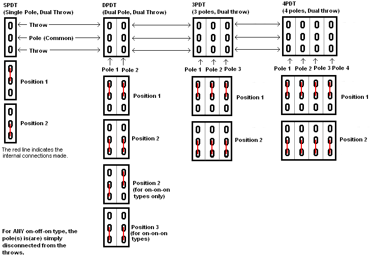
Let's say I have a 4 coil pickup, where the "neck" and "bridge" coil pairs are wired in series, and there's also a "tap" lead that comes from in between each coil pair. I'd like to know if there's a way to use a 3 position DPDT on-on-on switch to do something like the following:

Assuming the neck coils are in series with each other, and the bridge coils in series with each other... I'd like to be able to switch between the following:
1) Neck pair in series with the bridge pair.
2) Neck pair in parallel with the bridge pair.
3) Bridge Coil 1 in series with Neck Coil 2 (much like a reverse P pickup... see image below).
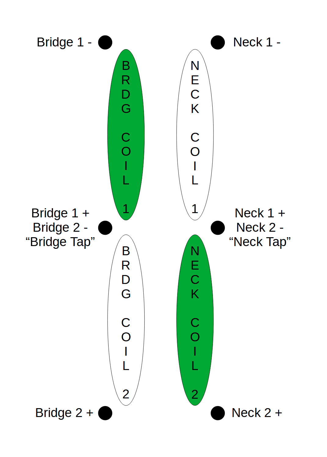
upload_2022-9-24_14-59-45.png


I know that in cases 1) and 2), the tap leads would be left unconnected. In case 3), the tap leads would be joined, and then "Neck 2 +" would be the hot lead, and "Bridge 1 -" would be the cold lead. I'm just unsure of how to accomplish this with a 3 position DPDT on-on-on switch (or if some other type of switch would need to be used).


Can any of you switching gurus lend a hand? ;-)
 

Attachments

  • upload_2022-9-24_14-56-22.png
    upload_2022-9-24_14-56-22.png
    96.3 KB · Views: 58
You need to start by making a truth table, then decide on a switch.

upload_2022-9-26_8-27-59.png


Notice that in the truth table, you have three connections changing. That requires a triple pole. You have three different states, so that is a triple throw. You can ignore the bridge tap column, because the changed state is connecting to the neck tap.

You need a TPTT switch (triple pole, triple throw).

Each pole on the switch has a Common. That is where you connect the wire from the column heading.

Position one on the switch is a short jumper wire between two poles.
Position two just needs ground and signal put in the right spots on the switch.
Position three has bridge tap wired to the right spot on the switch.
 
You need to start by making a truth table, then decide on a switch.

View attachment 4825502

Notice that in the truth table, you have three connections changing. That requires a triple pole. You have three different states, so that is a triple throw. You can ignore the bridge tap column, because the changed state is connecting to the neck tap.

You need a TPTT switch (triple pole, triple throw).

Each pole on the switch has a Common. That is where you connect the wire from the column heading.

Position one on the switch is a short jumper wire between two poles.
Position two just needs ground and signal put in the right spots on the switch.
Position three has bridge tap wired to the right spot on the switch.


Thanks for this!

Now I just need to try and make sense of it, and map that to what needs to happen on a switch.

Also, would that need to be a TPTT on-on-on? On-off-on?
 
@MidlifeBeginner is right. 3P3T ON-ON-ON is what you need, but in a toggle those are rare things. I would recommend rotary. Quick search finds some of these on eBay. Quality is uncertain though so YMMV.

Edit: A cheap/readily available alternative would be two DPDT switches (S/P and coil tap). You can get those on push-pull pots for a less cluttered appearance.
 
Last edited:
  • Like
Reactions: slowburnaz
Hmm…. I guess maybe I need to just go with having 2 of those options on a switch. Such as Neck and Bridge coils in series, and Bridge 1 in series with Neck 2 (reverse P-ish).

I think a DPDT on-off-on could be used for that, eh?

OK, then the switch would essentially just be a coil tap. A simple SPST would work for that, although if you wanted the kill (off) position you would need a SPDT on-off-on. With an on-off-on switch one way would be all 4 coils in series, the other way would be bridge 1 in series with neck 2, and the middle would be off (no sound).
 
Last edited:
It would need to be a 3PDT for that. You still have three connections that are changing. So, you need 3 poles.

3PDT toggles are much easier to find than 3P3T.

Not really. Neck 1 - always connects to bridge 2 + so no need to switch that. All that needs to be switched is whether neck 2 - goes to neck 1 + or bridge 1 +, which can be done with a SPDT.
 
  • Like
Reactions: slowburnaz
26845030[/URL], member: 286020"]Not really. Neck 1 - always connects to bridge 2 + so no need to switch that. All that needs to be switched is whether neck 2 - goes to neck 1 + or bridge 1 +, which can be done with a SPDT.


I get the feeling that I’m screwed if the tap connections are shared by the coils? Meaning, for example, Neck 1 - and Neck 2 + are connected internally on a PCB…. ?

Or am I still misunderstanding something?


Kinda seems like maybe since those are internally connected, that I’d also need a way of switching which “-“ lead goes to ground.
 
Last edited:
Nevermind...

I think I've got it.

If I use Neck 2 + as my hot lead, and Bridge 1 - as my cold (to ground) lead, and connect Neck 1 - to Bridge 2 +, that handles the series configuration. Then, I guess, the switch would either connect Neck Tap to Bridge Tap, or leave that connection open. When the tap connections are joined, the path of least resistance is through Neck Coil 2 and Bridge Coil 1.

Is that right?
 
  • Like
Reactions: Jeff Siddall
Nevermind...

I think I've got it.

If I use Neck 2 + as my hot lead, and Bridge 1 - as my cold (to ground) lead, and connect Neck 1 - to Bridge 2 +, that handles the series configuration. Then, I guess, the switch would either connect Neck Tap to Bridge Tap, or leave that connection open. When the tap connections are joined, the path of least resistance is through Neck Coil 2 and Bridge Coil 1.

Is that right?

Exactly! The switch is effectively just shorting the bridge 2 and neck 1 coils.
 
  • Like
Reactions: slowburnaz
Thanks for all your help, you two!

Though, now that I think about it, I think the ultimate option would be to use a 4 way rotary to enable the following:
1) All coils in series
2) Reverse "P" config
3) Standard "P" config
4) Neck and Bridge coil pairs in parallel

Any pointers there? ;-) Those rotary switches confuse the hell outta me.
 
Make a truth table first. You use that for checking things with a multimeter after wiring.

Think of each pole as a separate switch. There is a common terminal for any pole. Th column heading from your truth table goes to the common.

This!

You should not be afraid of rotary switches. The open frame ones are easy because you can see exactly what connects where just by looking at it. Here is an animation of a 4P6T switch:

rotary_switch-4P6T.gif


You would only have 4/6 of the throws in the picture above so even simpler. Exactly how many poles you need would be something you have to figure out.

Think of the poles as "the things to connect" and the 4 throws as "the 4 places they connect to". Then assign a pickup configuration to each of the 4 throws and work out which "places" everything needs to connect for that configuration.

Good luck!
 
Though, now that I think about it, I think the ultimate option would be to use a 4 way rotary to enable the following:
1) All coils in series
2) Reverse "P" config
3) Standard "P" config
4) Neck and Bridge coil pairs in parallel

I decided to resurrect this thread instead of replying to the other guy's thread...
But, I'm looking for a visual diagram for how to wire up a 4-way rotary switch like this.
Hey, schematics *ARE* visual diagrams! :D This is all you're gonna get for free.

Turner-P-upV2 (2).png


This could also be implemented with a 5-way, 4 pole "super switch" Stratocaster style blade switch; blade switches are a re-packaged rotary switch.
 
  • Like
Reactions: fig
I decided to resurrect this thread instead of replying to the other guy's thread...
Hey, schematics *ARE* visual diagrams! :D This is all you're gonna get for free.

View attachment 5032559

This could also be implemented with a 5-way, 4 pole "super switch" Stratocaster style blade switch; blade switches are a re-packaged rotary switch.

Ha! Right on! Thanks.
 
  • Like
Reactions: Crater