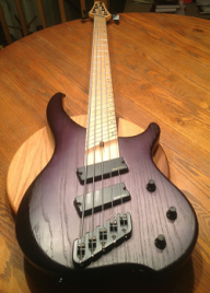
Dingwall Combustion Modification
Series/Parallel Switching plus added Mid Sweep
Parts:
2 mini DPDT On-On switches. (~$3)
1 John East Mid Sweep (~$115)
1 Stacked Log Taper Pot (1M ohm if you can find it, but I used 500k and it sounds great.)
22 gauge wire in several colors. It doesnt matter what colors, as long as you can keep track of it. (Though if you want that retro sound, it has to be purple.)
Tools:
Phillips head screwdriver
Needle Nose pliers
Drill press (A hand drill will work, but a drill press will provide cleaner results)
Clamps (if using a drill press)
Soldering iron, solder.
Razor blade
Wire stripper
Time, concentration, and patience.
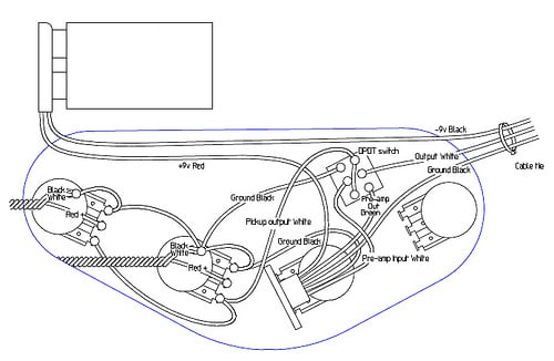
Here's the initial diagram:
Here's where we're going to end up.

Steps:
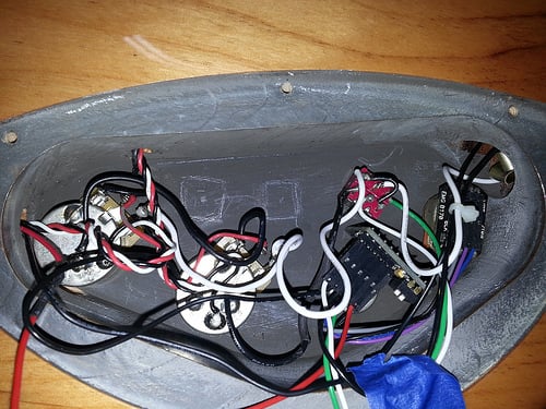
Start by removing the strings. Next, open the Control cavity and take some detailed pictures of the current wiring and setup in case you get confused. I referenced my initial pictures several times.
Carefully cut the tiny zip tie holding the wires together. Pull the wires gently back and out of the way so you can see the extra space you have in the cavity. Some blue painters tape or Low tack tape works great for holding the wires out of the way without gumming up or damaging your finish.
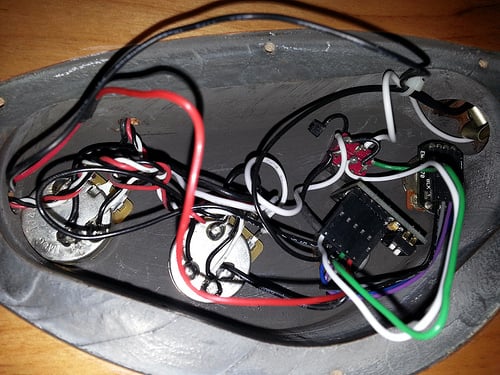
Take your two mini toggle switches and place them into the control cavity where you would like to mount them. Think about how they should be spaced to look good on the front of the bass. Since there are four knobs, I figured that putting one switch in between each pair of knobs would look good, plus thats where there is space. Keep in mind the spacing between these two switches, the pots, and the active/passive switch thats already in there. You will need a bit of space between the components so dont put them too close to each other or to the walls of the cavity, otherwise you may not have space for the wires, or to rotate the switches to the most comfortable angle.
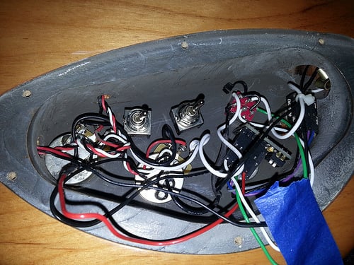
Now, once youve decided on your placement, either use a grease pencil or a regular pencil to gently mark the outline of your switches. Be sure not to scratch off the paint thats in there, it is a conductive paint that helps shield the cavity and keep out extra noise. Once you have your outlines drawn, remove the switches and draw a dot right in the center of the square youve drawn. This will be the point where you eventually drill.
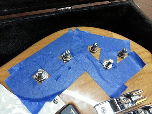
Now that you have your placement all worked out, its time to begin removing the electronics. Start by removing each of the knobs on the front of the bass, then use pliers to loosen the nuts holding the pots in place. I laid down some painters tape around the area because Im pretty confident in my own ability to let the pliers slip and mar a beautiful finish. I figure an extra minute of time is worth it. I would suggest using your fingers to remove the nuts as soon as they are loose enough to minimize the risk of damaging the finish.
Once the nuts have been removed, the first part to remove is the active/passive switch. This switch is basically what you should be modeling your other switches on. I couldnt find an exact match, but I got reasonably close.
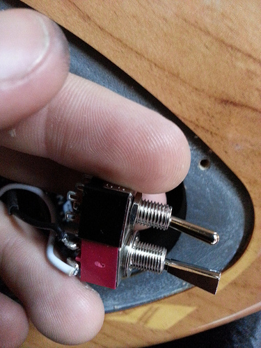
The biggest concern with these mini toggles is whether the shaft is long enough to reach all the way through the bass. Now is a good time to remove the Active/Passive switch and compare the two side by side. It would also be prudent to try putting the new switch through the hole where the Active/Passive switch was to ensure that it reaches far enough through. If not, you can still put everything back with a minimum of effort until you have the correct parts.
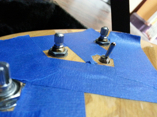
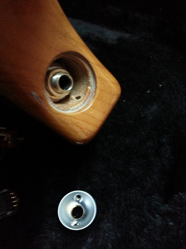
Next, continue pulling each of the pots out of their holes. Once all of the pots are cleared, you can remove the output jack. This is done by first removing the two screws that hold it in. Next, you have to rotate the silver cup to unscrew it from the jack. I did this using the pair of needle nose pliers. After a moment, I realized itd be a good idea to wrap the tips in tape uncase I slipped. If you have nylon tipped tweezers or needle nose pliers, those would probably work great. So rotate the cup counterclockwise to unscrew it from the jack, pull the cup out of the bass, then gently work the jack back out into the control cavity.
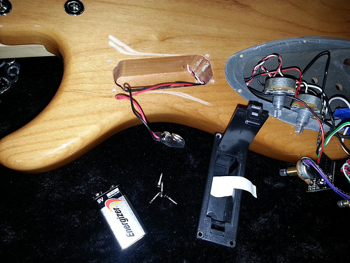
Now all of your control cavity components should be free. Open up the battery compartment and remove the battery. You can unscrew the four small screws holding the plastic battery compartment in place, and then squeeze the battery connector through the small gap in the plastic casing to remove the case entirely.
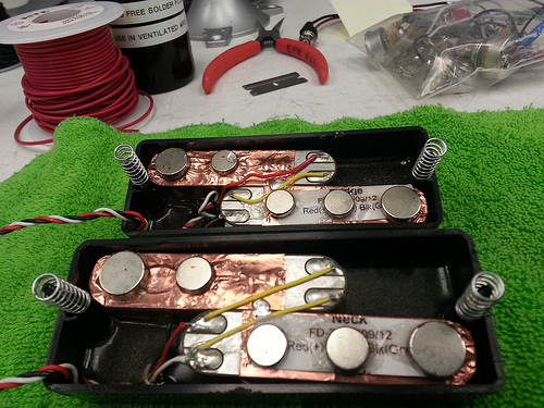
Now its time to unscrew and begin removing the pickups. It may be a good idea to take a picture of the way each of the pickups is wired for future reference should you want to revert to the stock configuration at some point. As you can see, the stock configuration is Parallel for the neck pickup and series for the bridge pickup.
Now, there should be three wires coming from each pickup, a red, a white, and a black wire. The red wire is the pickup Hot (+) signal, white is the Cold (-) signal, and black is the pickup shield ground wire. You will see that for each pickup, these wires go through into the control cavity and connect to their volume pot. The red wire is connected to the center pin, and the black and white wires are both grounded to the cover of the pot.
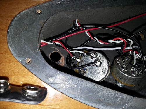
Desolder all three of these wires from the neck pickups volume pot so that they can be pulled through towards the pickup and it can be pulled free. Repeat this for the Bridge pickup.
The only thing left holding the electronics into the instrument now is the battery connector. Since we are going to be splicing an extra wire onto this later anyway (if you are adding the John East Mid Sweep), I decided to just cut both the red and black wires in a place where it would be convenient to work on later. If you arent adding the mid sweep and are just adding the series parallel switches, you could probably desolder the black wire from the output jack and unplug the red wire from the EMG preamp (though I didnt try this, so Im unsure if that wire will come out individually.
Drilling
**Note that if you are just adding the series/parallel functionality and not the Mid Sweep, a great option would be to just replace the current Volume controls for each pickup with Push/pull pots with built in DPDT switches. This means you dont have to drill any extra holes.
You should now have successfully removed all the electronic components from the instrument. Time to get drillin! As mentioned earlier, using a drill press really is the way to go for this. You will get much more reliable, clean results and not have to worry about whether you drilled at an angle. For my setup I laid a good thick stack of shop towels on the stage underneath my instrument, leaving a small gap where the drill would penetrate.
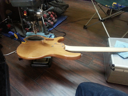
This ensures that you wont damage the finish or the instrument by clamping it or scraping it along a hard surface.
Do you still have some tape on the front side of the instrument from earlier? If not, putting a strip or two of tape over the area where the switches will be will help diminish any chance of tearout or chipping from the drilling process.
Now, put a small pilot bit in the press and lay the instrument face down on the stage so that you can line up the bit to drill exactly where you made the mark in the control cavity earlier. Now, be sure to use a very small bit for this step, this wont be our final hole, it is just a pilot hole for alignment. Once you have the instrument lined up under the drill bit just how you want it, gently but firmly clamp it with some rubber padded clamps, or a regular clamp with some sort of cloth in between to protect the finish.
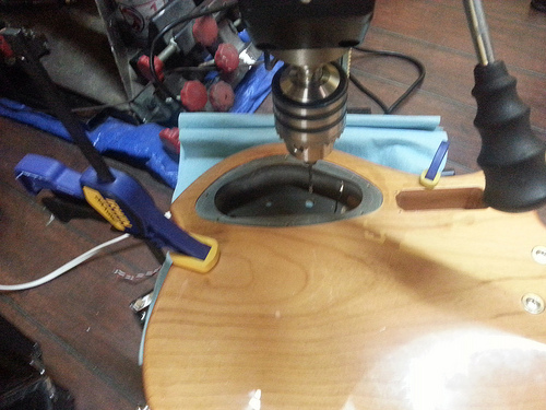
Now, turn on the drill press and slowly with gentle pressure, drill down through the cavity all the way to the finished front of the bass. Release the clamps, align for the next hole, reclamp, and drill the second hole. Now you should have two small, clean holes all the way through the instrument.
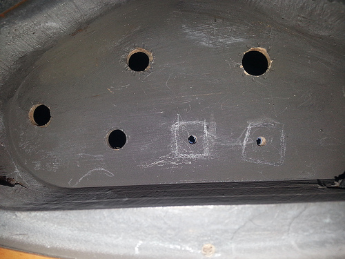
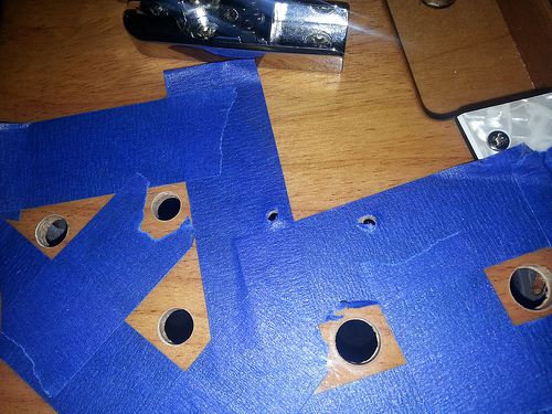
Now we will drill the final holes. First, select a drill bit just a bit larger than the diameter of the threaded post of your mini switches. You dont want this to bind when passing through the instrument; the nut will hold it in place. The next step is very important to ensure there is no tearout on the face of the bass. For the last holes, we drilled from the instrument cavity to the face of the bass, but for this step we want to do the opposite. When drilling through wood there is a good chance that as the drill gets to the opposite edge, it may tear out little chips of wood and finish if we arent careful, especially if we are drilling larger diameter holes. Now we obviously dont want this to happen so we will drill the final holes from the face of the bass into the control cavity. This will ensure that if there is any tearout, it will be inside the control cavity where no one can see it. If youre worried about that, you can place a bit of tape inside the control cavity across our pilot holes to help minimize the chance even further. Now repeat the process of aligning the instrument to the drill bit, this time using the existing pilot hole to align to. Clamp the instrument in place, and slowly with gentle pressure lower the drill bit through the wood.
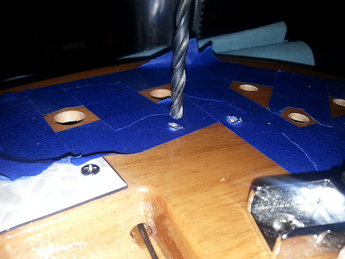
Repeat for the second hole. Remove any tape and admire your handiwork.
Notice how I had just a little tearout on the control cavity side of the hole, but the front face looks very clean.

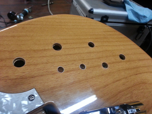
Even if you do get a little roughness, chances are pretty good that itll be hidden beneath the control knobs anyway.
Congratulations on successfully getting the holes drilled! Now its time for the wiring.
Series/Parallel Switching plus added Mid Sweep
Parts:
2 mini DPDT On-On switches. (~$3)
1 John East Mid Sweep (~$115)
1 Stacked Log Taper Pot (1M ohm if you can find it, but I used 500k and it sounds great.)
22 gauge wire in several colors. It doesnt matter what colors, as long as you can keep track of it. (Though if you want that retro sound, it has to be purple.)
Tools:
Phillips head screwdriver
Needle Nose pliers
Drill press (A hand drill will work, but a drill press will provide cleaner results)
Clamps (if using a drill press)
Soldering iron, solder.
Razor blade
Wire stripper
Time, concentration, and patience.
Here's the initial diagram:
Here's where we're going to end up.
Steps:
Start by removing the strings. Next, open the Control cavity and take some detailed pictures of the current wiring and setup in case you get confused. I referenced my initial pictures several times.
Carefully cut the tiny zip tie holding the wires together. Pull the wires gently back and out of the way so you can see the extra space you have in the cavity. Some blue painters tape or Low tack tape works great for holding the wires out of the way without gumming up or damaging your finish.
Take your two mini toggle switches and place them into the control cavity where you would like to mount them. Think about how they should be spaced to look good on the front of the bass. Since there are four knobs, I figured that putting one switch in between each pair of knobs would look good, plus thats where there is space. Keep in mind the spacing between these two switches, the pots, and the active/passive switch thats already in there. You will need a bit of space between the components so dont put them too close to each other or to the walls of the cavity, otherwise you may not have space for the wires, or to rotate the switches to the most comfortable angle.
Now, once youve decided on your placement, either use a grease pencil or a regular pencil to gently mark the outline of your switches. Be sure not to scratch off the paint thats in there, it is a conductive paint that helps shield the cavity and keep out extra noise. Once you have your outlines drawn, remove the switches and draw a dot right in the center of the square youve drawn. This will be the point where you eventually drill.
Now that you have your placement all worked out, its time to begin removing the electronics. Start by removing each of the knobs on the front of the bass, then use pliers to loosen the nuts holding the pots in place. I laid down some painters tape around the area because Im pretty confident in my own ability to let the pliers slip and mar a beautiful finish. I figure an extra minute of time is worth it. I would suggest using your fingers to remove the nuts as soon as they are loose enough to minimize the risk of damaging the finish.
Once the nuts have been removed, the first part to remove is the active/passive switch. This switch is basically what you should be modeling your other switches on. I couldnt find an exact match, but I got reasonably close.
The biggest concern with these mini toggles is whether the shaft is long enough to reach all the way through the bass. Now is a good time to remove the Active/Passive switch and compare the two side by side. It would also be prudent to try putting the new switch through the hole where the Active/Passive switch was to ensure that it reaches far enough through. If not, you can still put everything back with a minimum of effort until you have the correct parts.
Next, continue pulling each of the pots out of their holes. Once all of the pots are cleared, you can remove the output jack. This is done by first removing the two screws that hold it in. Next, you have to rotate the silver cup to unscrew it from the jack. I did this using the pair of needle nose pliers. After a moment, I realized itd be a good idea to wrap the tips in tape uncase I slipped. If you have nylon tipped tweezers or needle nose pliers, those would probably work great. So rotate the cup counterclockwise to unscrew it from the jack, pull the cup out of the bass, then gently work the jack back out into the control cavity.
Now all of your control cavity components should be free. Open up the battery compartment and remove the battery. You can unscrew the four small screws holding the plastic battery compartment in place, and then squeeze the battery connector through the small gap in the plastic casing to remove the case entirely.
Now its time to unscrew and begin removing the pickups. It may be a good idea to take a picture of the way each of the pickups is wired for future reference should you want to revert to the stock configuration at some point. As you can see, the stock configuration is Parallel for the neck pickup and series for the bridge pickup.
Now, there should be three wires coming from each pickup, a red, a white, and a black wire. The red wire is the pickup Hot (+) signal, white is the Cold (-) signal, and black is the pickup shield ground wire. You will see that for each pickup, these wires go through into the control cavity and connect to their volume pot. The red wire is connected to the center pin, and the black and white wires are both grounded to the cover of the pot.
Desolder all three of these wires from the neck pickups volume pot so that they can be pulled through towards the pickup and it can be pulled free. Repeat this for the Bridge pickup.
The only thing left holding the electronics into the instrument now is the battery connector. Since we are going to be splicing an extra wire onto this later anyway (if you are adding the John East Mid Sweep), I decided to just cut both the red and black wires in a place where it would be convenient to work on later. If you arent adding the mid sweep and are just adding the series parallel switches, you could probably desolder the black wire from the output jack and unplug the red wire from the EMG preamp (though I didnt try this, so Im unsure if that wire will come out individually.
Drilling
**Note that if you are just adding the series/parallel functionality and not the Mid Sweep, a great option would be to just replace the current Volume controls for each pickup with Push/pull pots with built in DPDT switches. This means you dont have to drill any extra holes.
You should now have successfully removed all the electronic components from the instrument. Time to get drillin! As mentioned earlier, using a drill press really is the way to go for this. You will get much more reliable, clean results and not have to worry about whether you drilled at an angle. For my setup I laid a good thick stack of shop towels on the stage underneath my instrument, leaving a small gap where the drill would penetrate.
This ensures that you wont damage the finish or the instrument by clamping it or scraping it along a hard surface.
Do you still have some tape on the front side of the instrument from earlier? If not, putting a strip or two of tape over the area where the switches will be will help diminish any chance of tearout or chipping from the drilling process.
Now, put a small pilot bit in the press and lay the instrument face down on the stage so that you can line up the bit to drill exactly where you made the mark in the control cavity earlier. Now, be sure to use a very small bit for this step, this wont be our final hole, it is just a pilot hole for alignment. Once you have the instrument lined up under the drill bit just how you want it, gently but firmly clamp it with some rubber padded clamps, or a regular clamp with some sort of cloth in between to protect the finish.
Now, turn on the drill press and slowly with gentle pressure, drill down through the cavity all the way to the finished front of the bass. Release the clamps, align for the next hole, reclamp, and drill the second hole. Now you should have two small, clean holes all the way through the instrument.
Now we will drill the final holes. First, select a drill bit just a bit larger than the diameter of the threaded post of your mini switches. You dont want this to bind when passing through the instrument; the nut will hold it in place. The next step is very important to ensure there is no tearout on the face of the bass. For the last holes, we drilled from the instrument cavity to the face of the bass, but for this step we want to do the opposite. When drilling through wood there is a good chance that as the drill gets to the opposite edge, it may tear out little chips of wood and finish if we arent careful, especially if we are drilling larger diameter holes. Now we obviously dont want this to happen so we will drill the final holes from the face of the bass into the control cavity. This will ensure that if there is any tearout, it will be inside the control cavity where no one can see it. If youre worried about that, you can place a bit of tape inside the control cavity across our pilot holes to help minimize the chance even further. Now repeat the process of aligning the instrument to the drill bit, this time using the existing pilot hole to align to. Clamp the instrument in place, and slowly with gentle pressure lower the drill bit through the wood.
Repeat for the second hole. Remove any tape and admire your handiwork.
Notice how I had just a little tearout on the control cavity side of the hole, but the front face looks very clean.
Even if you do get a little roughness, chances are pretty good that itll be hidden beneath the control knobs anyway.
Congratulations on successfully getting the holes drilled! Now its time for the wiring.
 Tada!
Tada!