I have my B-15 on the bench giving it some much needed love. My question is about the bias diode. The schematics have a part number of 10 D 6 for the diode. I cannot find any data on this creature. I don't want to assume that a 1N4007 is a suitable replacement until I know more about the diode in the circuit. Any help would appreciated.

Enjoy the benefits of a premium membership!
Upgrade Account
-
TalkBass has been independent since 1998. Add your voice.
Create a free account to reply to discussions, view embedded media, and browse with fewer display ads.
Join free Log in
Want zero display ads or expanded classifieds tools? Compare plans.
You are using an out of date browser. It may not display this or other websites correctly.
You should upgrade or use an alternative browser.
You should upgrade or use an alternative browser.
1965 Ampeg B-15NF Bias Diode
- Thread starter dgaggi
- Start date
More options
Who Replied?
- Feb 13, 2008
- 1,247
- 1,916
- Disclosures
- Owner, Vintage Blue (repro cabinets)


Ah ha! Never mind. Found the data on this rascal and no, a 1N4007 would not work.
A 1N4007 will be fine. Check or replace the high wattage resistor and the cap in that circuit.

Is the diode bad?I have my B-15 on the bench giving it some much needed love. My question is about the bias diode. The schematics have a part number of 10 D 6 for the diode. I cannot find any data on this creature. I don't want to assume that a 1N4007 is a suitable replacement until I know more about the diode in the circuit. Any help would appreciated.

- Feb 12, 2006
- 60,977
- 5
- 220,730
- Disclosures
- Development Engineer-Mesa Boogie, Development Engineer-Genzler (pedals), Product Support-Genz Benz
Agreed, don't replace parts that aren't bad.
For the negative bias voltage circuit, a 1N4003, 1N4004 or 1N4007 is fine.
For the negative bias voltage circuit, a 1N4003, 1N4004 or 1N4007 is fine.
I'm going to check the voltage off of the diode once it's recapped. I wanted to know what to use to replace it if the voltage was off. I'm going through this amp with a fine tooth comb. The last tech that was in here was less than stellar. This is what it looked like when I opened it up. Yes. That big honkin' blue cap to the right is the bais cap. 220uf 350VDC.  I guess they couldn't find the filter cap of the right voltage/value so they put two sprague 20uf in parallel, which is close but is less than aesthetic. The Mallory can cap has never been touched. That's a ticking time bomb at 58 years old. The solder work looks like they used a bic lighter. I'm going through every solder joint and either reflowing or redoing them. It's getting much love and will be a solid amp when I'm through. Not in a hurry and want to do things right.
I guess they couldn't find the filter cap of the right voltage/value so they put two sprague 20uf in parallel, which is close but is less than aesthetic. The Mallory can cap has never been touched. That's a ticking time bomb at 58 years old. The solder work looks like they used a bic lighter. I'm going through every solder joint and either reflowing or redoing them. It's getting much love and will be a solid amp when I'm through. Not in a hurry and want to do things right.Attachments

- Feb 12, 2006
- 60,977
- 5
- 220,730
- Disclosures
- Development Engineer-Mesa Boogie, Development Engineer-Genzler (pedals), Product Support-Genz Benz
Everything appears to be original under the chassis except for the large electrolytics. Don’t change the green caps. The small blue one should be original. The old Mallory cap cans often don’t last 58 years in these amps.
The bias is adjusted by changing a resistor. There are details in the TB Portaflex Wiki.
Technical - Amplifier | TalkBass.com
The bias is adjusted by changing a resistor. There are details in the TB Portaflex Wiki.
Technical - Amplifier | TalkBass.com
Yup! Only changing out the electrolytic caps. The Mallory can has been in for 56 years. My math was off. The amp is two years older than me. lol The Ducati cap 25uf 30vdc is getting replaced. I've been on the wiki and I'm adding the bias adjust circuit just to make adjusting the bias easier for future output tube changes. I've also ordered the tone boards and components. I'm not too sure if I'm going to do the tone board mod. The tone circuit, from what I've measured on channel one, it is a bit out specs. I'll get an ESR meter on the caps to see if they are still good. I may do one channel depending on how it sounds after the overhaul. The last tech also defeated the Ampeg safety circuit. You can see the ground side of the 25uf cap is jumpered over to the 1k resistor in that circuit. That is the hot mess on the right side where the red, black and white wires go to the board. It's amazing this output transformer hasn't been taken out by someone unplugging the speaker from the cabinet while it's not in standby. Hopefully with the recap it will last at least until the end of my life time.  This amp sounded incredible as it was, albeit a bit noisy. I haven't used it because I could hear that it was on borrowed time. I can't wait to hear it when I'm done. Should be epic! I'll keep posting on my progress as I go through it.
This amp sounded incredible as it was, albeit a bit noisy. I haven't used it because I could hear that it was on borrowed time. I can't wait to hear it when I'm done. Should be epic! I'll keep posting on my progress as I go through it.
Last edited:
- Feb 12, 2006
- 60,977
- 5
- 220,730
- Disclosures
- Development Engineer-Mesa Boogie, Development Engineer-Genzler (pedals), Product Support-Genz Benz
The small caps in the tone circuit almost never fail or drift.
How do you know that the amp even met whatever specs you are quoting? Often amps of that era were just close enough because the natural tolerances of the parts was 10-20%.
My suggestion is to leave those things alone and just address the things that NEED to be addressed first, you will probably discover that the other perceived issues are not real world issues.
How do you know that the amp even met whatever specs you are quoting? Often amps of that era were just close enough because the natural tolerances of the parts was 10-20%.
My suggestion is to leave those things alone and just address the things that NEED to be addressed first, you will probably discover that the other perceived issues are not real world issues.
People defeat the safety circuit so that they can use the head with any 8 ohm cab. They had several revisions of how the safety circuit worked. The regulatory agency asked them to revise it and make the safety circuit safe. They eventually did away with the concept. In later amps they simply had a 250 ohm @10W resistor from the 16 ohm output transformer tap to ground. It wasn’t intended to be a dummy load but it provided a bit of grace time to protect the amp till the player realized something was wrong.
A good thing about the adjustable bias circuit board is that it is fully reversible.
A good thing about the adjustable bias circuit board is that it is fully reversible.
Never quoted specs. Just reading what it should be as per the schematics and the tolerances. The plan for now is getting it back to being solid and going from there. I'm not going to change the tone boards out unless something is bad. Figured while I was ordering the bias boards that I would just go ahead and get the tone boards to have on hand. Even if I do change them, it will be reversable. 23 years as an electronic tech and Navy trained solder tech down to micro/miniature. I have the skills to get them out without cutting the leads or damaging them, if need be.The small caps in the tone circuit almost never fail or drift.
How do you know that the amp even met whatever specs you are quoting? Often amps of that era were just close enough because the natural tolerances of the parts was 10-20%.
My suggestion is to leave those things alone and just address the things that NEED to be addressed first, you will probably discover that the other perceived issues are not real world issues.
Last edited:
Yeah, I like that about the bias circuit also. ..and it's better than messing around and hooking up a decade resistor to find that sweet spot and then repeating that process the next time you change output tubes. A little dab of locktite or white out on the head after adjustment and done. The tone boards are also reversable. Just need to be careful, watch the heat and take your time de-soldering them.People defeat the safety circuit so that they can use the head with any 8 ohm cab. They had several revisions of how the safety circuit worked. The regulatory agency asked them to revise it and make the safety circuit safe. They eventually did away with the concept. In later amps they simply had a 250 ohm @10W resistor from the 16 ohm output transformer tap to ground. It wasn’t intended to be a dummy load but it provided a bit of grace time to protect the amp till the player realized something was wrong.
A good thing about the adjustable bias circuit board is that it is fully reversible.
Last edited:
I'm going to check the voltage off of the diode once it's recapped. I wanted to know what to use to replace it if the voltage was off. I'm going through this amp with a fine tooth comb. The last tech that was in here was less than stellar. This is what it looked like when I opened it up. Yes. That big honkin' blue cap to the right is the bais cap. 220uf 350VDC.
This is why I bitch about the quality of most of the techs out there; just too many damn hacks.
Part of the problem is the plethora of cheap, throwaway gear, and many people don't want to pay what it costs to properly fix things. So the demand for quality work is not there like it used to be and a lot of hacks are in the business.
Don't get me started on the aging out of the amp/pro audio tech workforce; many of the guys still doing this are older than I am!
You sound like you are one of the rare good guys, great on you for doing a proper job!

Analogeezer
Totally agree geezer. I've fixed modern amps that cost hundreds on their way to the scrap heap because of an inexpensive part. I much prefer vintage tube amps though. They each seem to have their own soul to me and I enjoy preserving the history. Good luck getting schematics for anything modern. I'm not big on mandates but I think if a company sells you something, they should give you everything you need to maintain it. Just seems ridiculous to me that they don't and flat out refuse to if you're not in their special circle of trust. Like I'm going to take their schematics and steal their crappy ideas. lol
It's the key component for the negative bias voltage.The diode doesn't have anything to do with the voltage.
While I hate to see butchered amps, there are some modifications that are worth performing. Of course, the work has to be done with care. Jess Oliver, the designer, used to service these amps and performed a number of upgrades on them. Things that he thought should be done.
ONE IMPORTANT SUGGESTION. CHANGE ONE THING AT A TIME AND TEST THE AMP AFTERWARDS.
Changing to a three-conductor power cord is a good idea. When doing so, test or remove the so called death cap. The black cap in the image above.
When this amp was designed, the Ampeg tubes sold at the time were inexpensive and pretty much plug-and-play. Resetting the bias was not usually necessary. Setting the bias required changing a resistor which meant soldering on the PCB. Today, tubes are expensive and less consistent. In order to optimize performance setting the bias when changing the power tubes is often required. Having a pot adjustable bias is a good feature. Another upgrade Jess performed and it's in all the modern Ampeg B-15 revisions.
There are known issues with these amps. The original Mallory cap can does not last 60 years, the rubber seal dries and cracks with the internal pressure. When amps that have sat unused for long periodsare put back into service, it can hasten the failure of this component.
The high wattage resistor in the bias circuit runs hot and tends to drift out of spec, both in the cathode and fixed bias revisions. The diode in the fixed bias revision is prone to failure.
The braid in shielded wires in the preamp is prone to rusting. The rusted areas tend to crack, this affects the shielding and leads to noise. Apexjr.com sells a very good one conductor shielded wire that I use.
A common issue is oxidation behind the input jack. This is the bus ground point and can make the amp hum. This point needs to be inspected and cleaned. Often the locking washer is so badly corroded that the plating is gone and it needs to be changed.
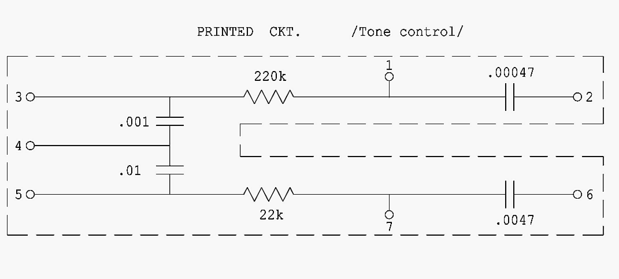
Baseed on my experience, the PEC tone control modules can have issues and should be inspected. They are an encased network of ceramic capacitors and carbon composition resistors. The tolerance of the resistors were +/- 20%, 1/5 Watt. The capacitor tolerance was +50% and -20% in the 1000mmF range, and +/- 20% in the 100mmF range. The working voltage of the capacitors was 450 VDC, 800 VDC flash.
Issues with these modules that I've seen include broken wires, cracks in the body, out of spec components. With two channels, ideally you want both models close to each other, they can be far apart. When a channel doesn't sound righ to my ears, it can sound muddy or what some call cloaked, changing this part can make the channel sound quieter and clearer. I don't condone changing them as a matter of course but sometimes it is necessary, even if the components read within spec
Some of these amps do not have grid stopper resistors on the first stage input of one of the channels (channel 2, intended for accordion). It can help with RFI pickup to install one.
Check the isolation washers on the jack on the back. The EXT SPKR jack shoud have an isolation washer set to avoid a ground loop. Amps with speaker cords are isolated, if this has been modified to install a jack, I like to isolate the jack rather than ground the return on the chassis. I find that the speaker return wire is quietest at phase inverter ground point on the bus.
The beauity of these amps is that if they are healthy, they can be very quiet. The quietest that I've heard. The tone is amazing.
ONE IMPORTANT SUGGESTION. CHANGE ONE THING AT A TIME AND TEST THE AMP AFTERWARDS.
Changing to a three-conductor power cord is a good idea. When doing so, test or remove the so called death cap. The black cap in the image above.
When this amp was designed, the Ampeg tubes sold at the time were inexpensive and pretty much plug-and-play. Resetting the bias was not usually necessary. Setting the bias required changing a resistor which meant soldering on the PCB. Today, tubes are expensive and less consistent. In order to optimize performance setting the bias when changing the power tubes is often required. Having a pot adjustable bias is a good feature. Another upgrade Jess performed and it's in all the modern Ampeg B-15 revisions.
There are known issues with these amps. The original Mallory cap can does not last 60 years, the rubber seal dries and cracks with the internal pressure. When amps that have sat unused for long periodsare put back into service, it can hasten the failure of this component.
The high wattage resistor in the bias circuit runs hot and tends to drift out of spec, both in the cathode and fixed bias revisions. The diode in the fixed bias revision is prone to failure.
The braid in shielded wires in the preamp is prone to rusting. The rusted areas tend to crack, this affects the shielding and leads to noise. Apexjr.com sells a very good one conductor shielded wire that I use.
A common issue is oxidation behind the input jack. This is the bus ground point and can make the amp hum. This point needs to be inspected and cleaned. Often the locking washer is so badly corroded that the plating is gone and it needs to be changed.
Baseed on my experience, the PEC tone control modules can have issues and should be inspected. They are an encased network of ceramic capacitors and carbon composition resistors. The tolerance of the resistors were +/- 20%, 1/5 Watt. The capacitor tolerance was +50% and -20% in the 1000mmF range, and +/- 20% in the 100mmF range. The working voltage of the capacitors was 450 VDC, 800 VDC flash.
Issues with these modules that I've seen include broken wires, cracks in the body, out of spec components. With two channels, ideally you want both models close to each other, they can be far apart. When a channel doesn't sound righ to my ears, it can sound muddy or what some call cloaked, changing this part can make the channel sound quieter and clearer. I don't condone changing them as a matter of course but sometimes it is necessary, even if the components read within spec
Some of these amps do not have grid stopper resistors on the first stage input of one of the channels (channel 2, intended for accordion). It can help with RFI pickup to install one.
Check the isolation washers on the jack on the back. The EXT SPKR jack shoud have an isolation washer set to avoid a ground loop. Amps with speaker cords are isolated, if this has been modified to install a jack, I like to isolate the jack rather than ground the return on the chassis. I find that the speaker return wire is quietest at phase inverter ground point on the bus.
The beauity of these amps is that if they are healthy, they can be very quiet. The quietest that I've heard. The tone is amazing.


