• TalkBass has been independent since 1998. Add your voice.
    Create a free account to reply to discussions, view embedded media, and browse with fewer display ads.
    Join freeLog in
    Want zero display ads or expanded classifieds tools? Compare plans.

1966 Ampeg B-15N issue - capacitors

I finallybought myself A B-15 and there is one thing that prevents me from starting it up.

The originall B-15 has a cigar-like capacitor, near its back end, my example has 2 replacement capacitors and no sign of the cigar-like one. I attach the pictures for you to check out what I mean.

I also cannot find the cigar one on the schematic of the NF. It is placed between two pins 8 of tubes of the power amp. (v4 and v5) and the pin 8 of the rectifier tube (v6). The smalll capacitors in my amp that seem to replace the big one are 100 uF each, at 450V.

I attach the photos in the reply, so that you know what I am talking about. [ampeg 1, 2, 3 - photos of my ampeg and here's a photo of the original Invalid Link Removed]

Is it safe to start the amp? Could you help me here, via talkbasS?? My tube amp maintenance guy is stuck and does not know whether he could start-up the amp without destroying it.


ps - the power transformer also has been replaced with the 70s tranny.
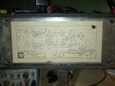
ampeg 3.jpg ampeg 2.jpg ampeg 1.jpg


EDIT: We've found out that the capacitors were not soldered properly, so they changed positions, here's how it looked before:

http://i.ebayimg.com/00/s/NjUyWDg2OQ==/z/hw0AAOSwq5lTnOe0/$_57.JPG

So there's that..
 
Last edited:

Those are axial electrolytic capacitors. Pin 8 on the output tube sockets are ground and pin 8 of the rectifier is your B+ high voltage supply. Those caps are replacing the original that comes off the rectifier I assume. I can't tell where the old one is or if it's been disconnected. Kind of a sloppy job but as long as nothing else is touching the cap leads you should be fine. And the two caps are wired in series which 2 100uF caps in series will give you a 50uF cap, the original is 40uF which is close enough.
 
  • Like
Reactions: Jack-Jack
I might be able to shed some additional light on what was done. The cigar like capacitor is what you see as the 30uF @ 600V, first node capacitor in the power supply. Note that the other power supply caps are 40uF @500V and these are in the silver capacitor can that sits on top of the chassis. For the first node after the rectifier, you want a higher voltage rating because when you turn on the amp and the caps are discharged, there is a voltage surge till the cap charges. So they make it 600V, a higher voltage rating is even better.

If you were to open the cigar shaped capacitor, you would see two series connected capacitors. This is exactly what you have in your amp. When you connect identical capacitors in series, the capacitance is halved and the rate voltage doubles. So in your case, two 100uF @ 450V in series will give you a 50uF @900V capacitance. So instead of a 30uF capacitor you have a 50uF capacitor. This will change the character of the amp a bit. The increased capacitance will give you a better bottom end and more headroom. BUT, and this is important, if you see a flash in the rectifier tube when you turn the amp on AND the cap is fully discharged, this is damaging your expensive rectifier tube. So check it carefully. It depends on the cap that is installed. If there's a problem, there are a few options: lower the capacitance, remove the tube rectifier and install a solid state rectifier module (details here), or add a couple of diodes, details here. If there isn't an issue now you will be ok but there may be a problem down the road when these caps are replace with new ones.

One source for replacement parts for these amps is Fliptops. Check out the TalkBass Portaflex Wiki, as well as the Portaflex Club for more info.
 
  • Like
Reactions: Jack-Jack
I'll let you know if we managed to launch the amp. It turned out that the solders did not take the Atlantic Ocean journey very well (USA -> Poland)

That's actually helping us a lot. I knew where to ask. Can't describe how grateful I am for your deep insight, based solely on the crappy photos...

You have restored my faith in humanity, seriously. It's nice to know that people are still able to be nice to each other. :)
 
I'd get some spaghetti on the leads of those axial caps at least, the lead on one looks dangerously close to a being able to short a resistor.

If there's nothing securing the caps physically to the chassis, put a dab of silicone on each side of those caps, to secure it to the board. Will prevent any issues from coming up due to transporting it around, you don't want those caps to move. Enjoy!
 
  • Like
Reactions: Jack-Jack
Cześć ! Your English is amazing !
Good luck with the Amp :)

Well, I have a major in English Linguistics, so that may be the main factor why I'm not bad at it ;)

I'd get some spaghetti on the leads of those axial caps at least, the lead on one looks dangerously close to a being able to short a resistor.

If there's nothing securing the caps physically to the chassis, put a dab of silicone on each side of those caps, to secure it to the board. Will prevent any issues from coming up due to transporting it around, you don't want those caps to move. Enjoy!

Yes, this is the solution we were thinking of. Put some silicone mass around them and problem solved.
 
  • Like
Reactions: Pimmsley
Grandpa's at home, I hope it's alive and kicking. I can't tell more since I don't have step down transformer here [230V->110V], but 2 hours ago it was sounding sweet. I will get my tranny on Wednesday probably, but I don't expect the unexpected. Thanks a mil for your help guys!

330d1g7.jpg
 
Great job on the repair upgrade. It feels better just looking at it! Note that you will need a pretty hefty (high current capacity) step-down transformer otherwise performance will suffer (as will the step-down x-former). I would be thinking about replacing the power transformer with one for 230v (keeping the original of course!). There may even have been an Ampeg 230v that could be used if found - try eBay?
 
  • Like
Reactions: Jack-Jack
Great job on the repair upgrade. It feels better just looking at it! Note that you will need a pretty hefty (high current capacity) step-down transformer otherwise performance will suffer (as will the step-down x-former). I would be thinking about replacing the power transformer with one for 230v (keeping the original of course!). There may even have been an Ampeg 230v that could be used if found - try eBay?


Regarding the external transformer - I got myself 400 Watts one, should be working ok, since the estimated power needs we assume are 330W (3,3A fuse in the back x 10). We also upgraded the external cab cable, since the original one was based on a 4-pin XLR plug. I wanted Bart to solder a simple jack plug there and he did it...

I really do not want to mess with the amp itself, since it's [besides the 70s tranny and the caps - which imho should be treated as the oil in your car] in almost immaculate condition.

Now I'm just hoping It won't be too loud to play at home :)
 
If volume at home is an issue, try an attenuator that goes between the head and cab. I use a weber mass on my bassman at home, works great. I got mine with a DI built in, makes recording or sound reinforcement nice and simple.
 
If volume at home is an issue, try an attenuator that goes between the head and cab. I use a weber mass on my bassman at home, works great. I got mine with a DI built in, makes recording or sound reinforcement nice and simple.

Invalid Link Removed

Would this one be enough? I know that the amp pushes out almost 35 Watts, but is it about the clean tone? I've heard that 35W is just clean power, and the distorted sound is more powerful watt-wise, but that may just as well be a myth.

Thanks for the useful advice. I'll find out how loud it iis tomorrow.
 
And I finally had a chance to try my '66 amp out...aaaaaaaand it sounds just like it should.

There's just one minor issue. The tubes are so hot that the lucite plate on their cover melts down. I played for like 15 minutes and the plate bent and there are some air bubbles inside. I'm going to get it replaced with a glass one, I don't think I'll be able to use the amp without the glowing logo.

You don't know whether the logo plates on the heritage b-15 are glass, do you? I have a friend who engraves things in glass with laser, could that be helpful?

Secondly - the cables in the back also seem to be melting from the tube warmth. Should I be worried?

But the tone - totally worth it!
 
I'd be thinking about making sure the tubes are being treated right by the amp rather than making a plan B for a melt-proof logo. If the 'stock' piece is being damaged by the heat of the tubes, that's a sign that something else is wrong and should be fixed.
 
It should not be getting that hot. It's running at the correct AC line voltage, and not trying to do 110v on a 220v or anything like that? If the line voltage is right, there's a serious problem with bias of the power tubes, they are getting way too much current somehow, incoming B+ could be too high or bias not set right, could be a short, lots of things really. I'd get it on a bench hooked up to a dummy load and get a look at the power section plate voltages and go from there. I assume the power tubes are red plating?
 

Latest posts