
• TalkBass has been independent since 1998. Add your voice.
    Create a free account to reply to discussions, view embedded media, and browse with fewer display ads.
    Join freeLog in
    Want zero display ads or expanded classifieds tools? Compare plans.

4 pot Wiring Diagram

Daniel109

Guest
Jun 10, 2014
47
20
36
New Zealand
What other options are there for wiring a Passive PJ bass with 4 pots?
so far Ive only found 2 different diagrams. Vol/Vol/Tone/Tone and Vol/Blend/Tone/Tone
I'm leaning more towards Vol/Blend/Tone/Tone.
is there anything wrong with this
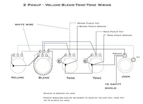
VBTT.jpg


Are there any better options(with diagrams) other than these 2?

I don't want to add an active EQ and I don't want to leave empty holes

Thanks

 
Having two tone controls really isn't a good idea. Unless you have an A/C taper blend that attenuates the pickups when they are used together, the controls both do the same thing, because they operate parallel to the signal path. The only ways around this are to add summing resistors, at the expense of output, or buffer, at the expense of needing a battery, and affecting the behavior of the blend. If you don't mind using an inferior blend pot, however, then go for it.

I would go for a master tone control and a bass cut control.
 
You could also use the fourth control space to put in a capacitor selector varitone- style to get more mileage out of your tone control. I like line6man's idea too, though.

You can do a lot with four control spaces. Phase switch, series/parallel switch, kill switch, dummy switch (my bass has two of these)
 
I like the capacitor selector switch idea, do different capacitors have that much noticeable effect on sound?
also what would a Phase switch do?

in your diagram m0ses is the bottom left the balance pot, or a switch?

is a bass cut like a tone but for the lows instead of the highs?
 
I like the capacitor selector switch idea, do different capacitors have that much noticeable effect on sound?
also what would a Phase switch do?

in your diagram m0ses is the bottom left the balance pot, or a switch?

is a bass cut like a tone but for the lows instead of the highs?

Capacitance affects the frequency cutoff. It's an extremely noticeable effect.
Phase switches put the pickups out of phase so that frequency content common to both pickups is cancelled out, leaving a thin, nasal tone. This is also a very extreme effect.

Yes, it's fair enough to say that bass cut pots are like tone controls for low frequencies.
 
So is M0ses's Diagram not correct? could you post one that is correct, (with the pots labeled) also, would the 2 capacitors need to be different, or the same, or doen't it matter.

Thanks for the help so far

I pointed out the errors in the diagram. When I get around to it, I can redraw it.
Here is one from Google, without the blend pot.
GL-Tone-Circuit.jpg


The value typically used for tone controls is 0.047uF, for passive, high impedance pickups. Some prefer different values, such as 0.022uF, 0.068uF or 0.1uF. It's all a personal preference. Bass cuts are not as common, so there isn't really a typical value, however, you will need something around an order of magnitude less capacitive, for the proper effect. AFAIK, G&L uses 0.0022uF capacitors for their bass cuts. Rickenbacker used 0.0047uF capacitors for the HPFs (fixed) on old 4001s.
 
Line6 will have to verify if I've gotten the pot terminals assigned correctly this time. I always get confused on that point, but I think I got it right this time.
a33d40941d8f9d249614bb1346020337.png


The rectangle with six circles is a blend pot drawn sideways so you can see the terminals easily. Next is the tone pot, the volume pot, and the bass pot, in that order.

I'm afraid I'm not sure how to calculate a cutoff frequency for the HPF, either, so someone else is gonna have to clue us in to what an appropriate capacitor value would be.
 
Line6 will have to verify if I've gotten the pot terminals assigned correctly this time. I always get confused on that point, but I think I got it right this time.
a33d40941d8f9d249614bb1346020337.png


The rectangle with six circles is a blend pot drawn sideways so you can see the terminals easily. Next is the tone pot, the volume pot, and the bass pot, in that order.

I'm afraid I'm not sure how to calculate a cutoff frequency for the HPF, either, so someone else is gonna have to clue us in to what an appropriate capacitor value would be.

Put the bass cut between the tone and volume.

It would be a waste of time trying to calculate frequency cutoffs, when your impedance is frequency-dependent. It's more productive to experiment with 0.0022uF, 0.0047uF, and other capacitances in that ballpark, to see what works best in practice.

for the Bass cut can i just use any pot?
I'm thinking of using the CTS "no load" pot for the tone, could i use that for the bass cut too, or would it not be suitable for either

The bass cut works by using a capacitor to block low frequencies, and then letting a pot bleed them back in to varying degrees. The use of a no-load pot would result in no signal bypassing the capacitor, and thus, the maximum amount of cut. As far as the value, the lower the resistance you choose, the less you will be able to cut, so a relatively high value, with an appropriate taper, is desirable. G&L uses 1M audio taper pots for this application.
 
So, this ?
a33d40941d8f9d249614bb1346020337.png


So I could use
250K blend pot
250K audio taper pot (for volume)
250K 'no load' audio taper pot (for tone)
1M audio taper pot (for bass cut)
0.022ufd for bass cut
0.47mfd for tone?

there are no 0.0022uf caps on the site I'm looking at
 
Last edited:

Latest posts