• TalkBass has been independent since 1998. Add your voice.
    Create a free account to reply to discussions, view embedded media, and browse with fewer display ads.
    Join freeLog in
    Want zero display ads or expanded classifieds tools? Compare plans.

70s Ampeg SVT re-valve and callibration

R6 looks original to me.
it should be pretty easy to determine that if you look at its solder connection on the other side of the board.

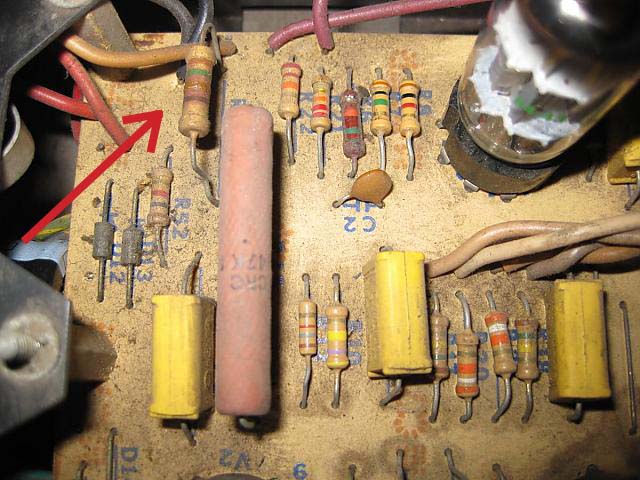
BTW, the resistor with the red arrow below should be checked (or replaced) since it's showing signs of overheating at one point:

IMG_0640.jpg
 
Yes as John pointed out, R50 looks like it might have a problem. Is it cracked or was there black on the metal plate over where this resistor is? It should be a 15K (brown green orange) 1 W resistor. R6 should also be a 15K resistor. For some reason, Ampeg seems to use a different type of resistor (carbon composition) in this position on a lot of these amps. I don't know why.

In your other photo you can see R35 and R36. These should be 1 ohm 5 W flame proof resistors. The values should be matched as close as possible. This allows you to closely match the two banks of power tubes when you are setting the bias. In older amps, the values can drift and sometimes need to be changed. If the two resistors are not exactly the same it is not a big deal.

It is good idea to keep the circuit board clean. Dirt on the circuit board can act as a conductor that can affect the performance of the amp. One way to clean it would be to use a Invalid Link Removed. You can dip Qtips (on the board and wires) and pipe cleaners (to get under the components and leads) into the solution and use them to clean. Sprays are available but can make a mess. You have to be careful to not remove the color bands on the resistors. This stuff tends to be gentler than alternatives such as 99% isopropyl alcohol (drug store) or methanol (hardware store).
 
Yes as John pointed out, R50 looks like it might have a problem. Is it cracked or was there black on the metal plate over where this resistor is? It should be a 15K (brown green orange) 1 W resistor. R6 should also be a 15K resistor. For some reason, Ampeg seems to use a different type of resistor (carbon composition) in this position on a lot of these amps. I don't know why.

In your other photo you can see R35 and R36. These should be 1 ohm 5 W flame proof resistors. The values should be matched as close as possible. This allows you to closely match the two banks of power tubes when you are setting the bias. In older amps, the values can drift and sometimes need to be changed. If the two resistors are not exactly the same it is not a big deal.

It is good idea to keep the circuit board clean. Dirt on the circuit board can act as a conductor that can affect the performance of the amp. One way to clean it would be to use a Invalid Link Removed. You can dip Qtips (on the board and wires) and pipe cleaners (to get under the components and leads) into the solution and use them to clean. Sprays are available but can make a mess. You have to be careful to not remove the color bands on the resistors. This stuff tends to be gentler than alternatives such as 99% isopropyl alcohol (drug store) or methanol (hardware store).

+1!

my '69 was easily 10X dirtier than your's before i cleaned it, but after carefully cleaning it, it looks pretty good now. i also replaced the filter caps, some resistors that were out of spec and a couple of bad coupling caps:

69svt-chassis-top-front-2.jpg


69svt-chassis-top-rear.jpg


69svt-chassis-bottom-front-1.jpg
 
Very nice John!

Looks like you put in heavier duty diodes and some silver mica caps.

I'm just starting work on a 71 model. I've been toying with the idea of using a cap board. This is one that I've used in other builds but I think that it is too big to fit in the SVT chassis. I like the Panasonic TS series caps that can be mounted on this board. The Invalid Link Removed from ExpressPCB is another possibility that looks interesting. Getting it to fit, possibly under the filament transformer, without the need to drill holes in the chassis is going to be the problem.
 
I'm just starting work on a 71 model. I've been toying with the idea of using a cap board.

i've recapped about 20 of them now, and i always just use spragues and the OEM multicap can type ones. there's not alot of room in there and i like them to look as original as possible.
 
i've recapped about 20 of them now, and i always just use spragues and the OEM multicap can type ones. there's not alot of room in there and i like them to look as original as possible.

That's what I usually do as well and keeping the original look is important.

I'm planning of keeping this amp so I thought that I might try a few things that are out of the ordinary. As long as they are fully reversible.

I've been wanting to experiment with boosting the cap values a bit to increase the amp's performance and decrease hum. Mostly I wanted to boost the A node cap from around 50 to 135uF. I thought that I would use two TS series 270uF caps on a cap board for that. The B node would be two series 100uF/450V caps. The others would be boosted slightly.

I also thought that I'd twist the heater lines and see if it makes a difference on this amp.


David