• TalkBass has been independent since 1998. Add your voice.
    Create a free account to reply to discussions, view embedded media, and browse with fewer display ads.
    Join freeLog in
    Want zero display ads or expanded classifieds tools? Compare plans.

79 Ampeg SVT Volume Drop

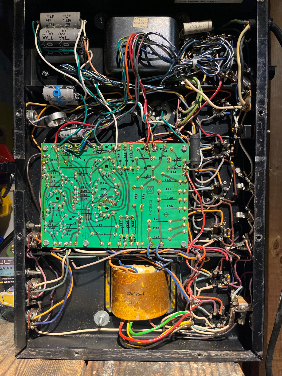
I have a 79 SVT I bought back in 99 or so. I was under the impression it was all original including full set of GE 6550s. In 2004 it got NOS GE JAN 6550s and a cap job. At that time it did lose some of it's signature growl but I assumed that was the tube set.

Amp hasn't had a ton of play time as I'm no longer gigging but I had no issues. Recently I was playing it and the amp randomly shut down... blown fuse. Replaced the fuse and amp worked but with weak volume and a bit more distortion. I swapped a 12DW7 in the power section and it briefly came back to life but after that session the amp returned to the weakened state.

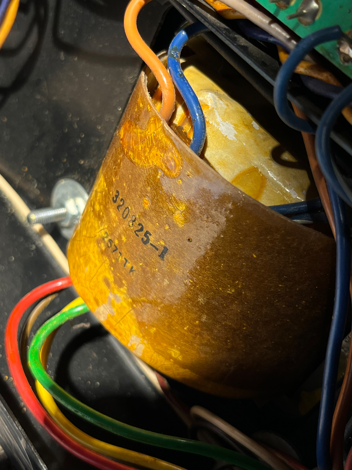
Took it to a friend with a tube tester and all the tubes tested good, except for the V1 12DW7. Amp in on the bench and I was surprised to see the Output Transformer had been changed with one that only noted 'Made in Japan'. Visual inspection shows no leaking caps or blown resistors. Cleaned the board and all tube sockets. Will begin to test values on resistors today. I do suspect the OT is failing and noticed that the outlet the amp was plugged into was not grounded for some reason.

Have others run into similar issue? Can anyone ID the replacement OT?
IMG_0381.jpg

IMG_0389.jpg

IMG_0390.jpg
 

Attachments

  • IMG_0381.jpg
    IMG_0381.jpg
    250.7 KB · Views: 63
  • IMG_0381.jpg
    IMG_0381.jpg
    250.7 KB · Views: 55
  • IMG_0381.jpg
    IMG_0381.jpg
    250.7 KB · Views: 54
Did the volume for channel two drop as well?

Channel 1 and Channel two are separate all the way to the 6C4 (V5). The 6C4 drives the Preamp Out on the back of the amp. Pretty sure that by 79, the Power Amp In jack was switching. So if you plug another preamp into the Power Amp In, it kills the signal coming from the Preamp.

I suggest that if you have another preamp to try it out into the Power Amp In. The idea is to determine if the problem is in the power amp or the preamp.

If you think it's in the preamp, then if both channels are weak it could be the 6C4. If only one channel is weak the problem is in that channel.

Another possibility is the preamp voltage comes from the power amp. If a capacitor is going bad it tends to drop the operating voltage too low. If the voltage is too low it reduces gain and headroom.

There are lethal levels of voltage in this amp. I have significant training in electronics trouble shooting and how to safely work with this level of voltage. If you do not have appropriate training, IMHO the best option is likely to take the amp to a tech. This is not a great amp to learn on.

If I was troubleshooting, I would start by checking operating voltages in the power supply. If you think the problem is in the power amp, check the bias test points and the working voltages on the output tubes. SVTs like to blow screen resistors when an output tube goes bad. The screen resistors are actually designed to act like fuses when you have a bad tube.

If the bias has dropped to approximately 2/3rd of the expected voltage or less, it typically indicates one or more tubes is dead or has caused the respective screen resistors to open. The see if all tubes are operating, I measure the voltage drop across the screen resistors. The voltage reading will tell me if the resistor is open. If the resistor is good the reading will also tell me how much current is flowing through the resistor.

If you think the problem is in the preamp, check the working voltages on the preamp filter cap and the tube sockets.

I don't think the Japanese OT is a problem. MTI era amps were made in Japan. From what I have read the quality of the transformers was very good.
 
Thank you. This is all helpful. Volume drop is the same across both channels. I had not considered the pre-amp and will look into that as well. Caps have been drained. I have been trained by my local tech (not on SVTs though).

I checked all screen resistors and they are all good. I checked all resistors and only R46 is bad (which runs to the OT).

I'll continue with measuring and then look into Pre-Amp.
 
upload_2022-8-21_15-15-49.png


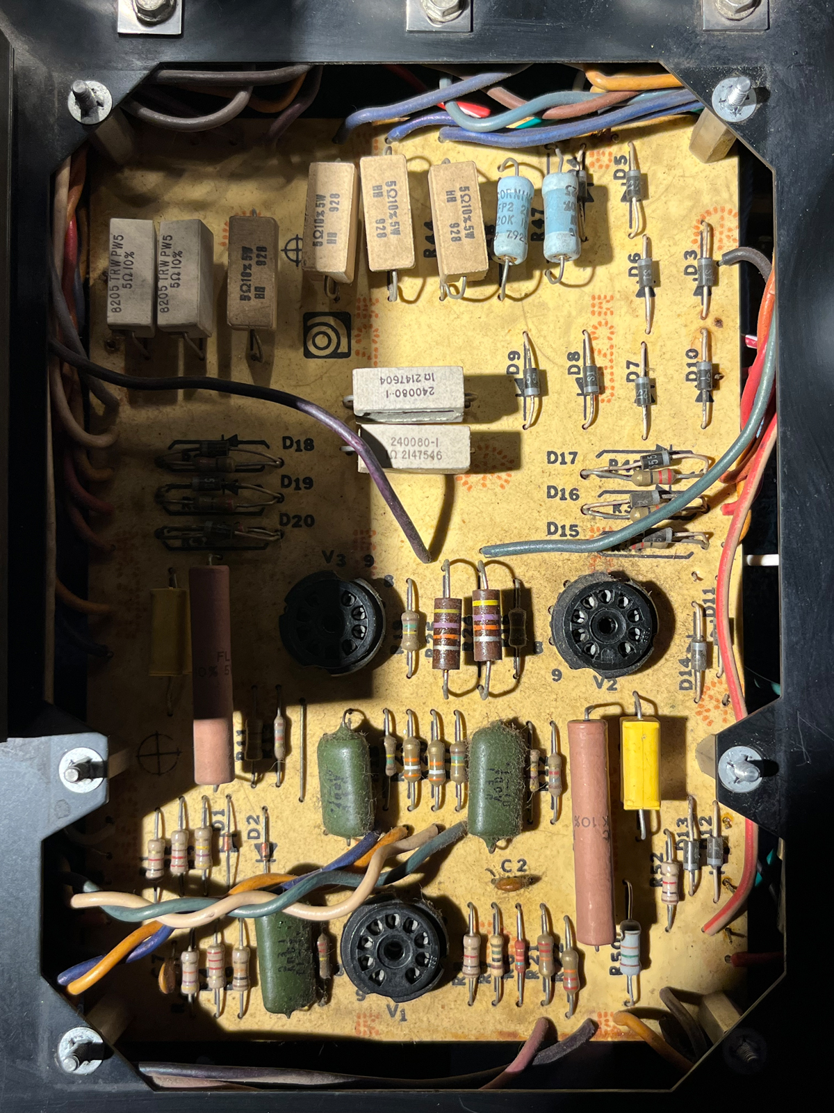
I labeled some of the components for you.

The screen diodes sort of protect the screen resistors. They were installed in some amps including the VR. When the amp is pushed the diodes can impact tone. Also if there is a hit, a diode may pull very high current which can damage the solder traces. Better for a screen resistor to fail IMHO--the diodes put the amp at risk of major damage to protect a part that costs a few cents.

The cathode and plate resistors are cement. When these fail, they tend to shoot out flames and hot gases through the channel that is cut in the bottom. See image below.
[Invalid or Expired Link Removed]
To prevent damage to the circuit board, the resistors should be elevated off the board, and the channel should be aimed away from the board. I believe it is also a good idea to elevate the screen resistors and to use flameless resistors.

Ampeg put out a technical service bulletin for modern SVTS in 2001 that removed the screen diodes and increased the value of the screen resistors from 22 ohms to 220ohms 1/2W. Probably a good idea to update the 79. The Vishay NFR25H has been recommended as good choice for the screen resistors: nfr25.pdf (vishay.com)
 
Thank you. This is all helpful. Volume drop is the same across both channels. I had not considered the pre-amp and will look into that as well. Caps have been drained. I have been trained by my local tech (not on SVTs though).

I checked all screen resistors and they are all good. I checked all resistors and only R46 is bad (which runs to the OT).

I'll continue with measuring and then look into Pre-Amp.

R46 and C7 form the global (negative) feedback loop. AFAIK, a problem here could cause a volume drop.
 
Another idea crossed my mind. It's seems odd that R46 would fail.

V1 lists 1.7V DC on the cathode. The cathode is connected to ground through 2.2K and 220 ohm resistors. The feedback loop connects between the two resistors.

Total resistance is 2420 ohms. Current = 1.7/2420 = 0.7mA

The voltage drop across the 220 ohm resistor is the voltage R46 should see.

The voltage drop = 0.0007 x 220 = 0.154V.

So as long as the DC voltage on the cathode of V1 is within spec, I don't think the source of the problem is DC.

So what could cause the failure? My guess is some sort of spurious oscillation. You won't necessarily hear an oscillation because it can occur at a frequency way above 20kHz. So you may need an O'scope to see it.

The oscillation may take most of the available power the amp can produce, so the amp may lose headroom. I would probably expect some sort of component failure fairly quickly after an amp breaks over into continuous oscillation. But if the oscillation only occurs on loud transients, it may sap headroom and take a while to cause a failure.

Just guesses.
 
  • Like
Reactions: AlexanderB
1001A3FE-C1B6-4DA0-8C0A-265B7E0AA93A.jpeg
Little luck today. 1 swapped the screen resistors for the 220k 1/2w. Replaced R46 and replaced R25 and R26 which were way high. Proper 47k’s are in there now.
Cleaned all boards, sockets and Preamp. Fired up and seemed to even have less power.

Drove to an hour to buy an old Eico 667 Tube Tester. Sadly that also doesn’t work so yet another project. Luckily much less complicated than the Ampeg.

Tomorrow I’ll test caps and OT. Will likely fully the recap the amp as I hate the messy piles of hopped small resistors. Would prefer 2 of the larger spragues.
 
Little luck today. 1 swapped the screen resistors for the 220k 1/2w. Replaced R46 and replaced R25 and R26 which were way high. Proper 47k’s are in there now.
Cleaned all boards, sockets and Preamp. Fired up and seemed to even have less power.

Drove to an hour to buy an old Eico 667 Tube Tester. Sadly that also doesn’t work so yet another project. Luckily much less complicated than the Ampeg.

Tomorrow I’ll test caps and OT. Will likely fully the recap the amp as I hate the messy piles of hopped small resistors. Would prefer 2 of the larger spragues.

Did you really only replace 1 screen resistor with 220 ohms and leave the others at 22 ohms as you posted?

Why don't you identify the actual cause first? The more that gets changed, the more variables you introduce.

Why would you recap the amp because you hate piles of hopped small resistors? Resistors and caps have nothing to do with each other.

My first suspicions would be the "recap job" that was done before. Yes, I see mistakes made all the time.

Take a signal generator and scope and look to see where you do not have the expected signal level... THAT's where you should start looking. As it is now, you have no idea if it's in the preamp or the power amp, how can you fix a preamp problem by changing parts in the power amp? That's why it's important to identify where the problem actually is.

I's also going to reiterate the warning to be VERY careful in that amp, there are voltages that can kill you (in not from the shock, than the fall and whatever falls on top of you).
 
View attachment 4788650
Ampeg put out a technical service bulletin for modern SVTS in 2001 that removed the screen diodes and increased the value of the screen resistors from 22 ohms to 220ohms 1/2W. Probably a good idea to update the 79.
I swapped the screen resistors for the 220k 1/2w. Replaced R46 and replaced R25 and R26 which were way high. Proper 47k’s are in there now.
Cleaned all boards, sockets and Preamp. Fired up and seemed to even have less power.
Was "220k" a typo in your post, or did you misread Wasnex's post? I'd expect a 220k screen resistor to significantly lower the power.
 
How much money can you throw in it? I don't play mine often, but had recapped it in 95, back then I didn't know what I do now. I am sure the filter caps are decent enough. I had to cobble a bit. It worked fine. Went through it again 2 years ago. Did a much better job. Blown fuse seems something shorted out, power tube, filter cap. Test all tubes, consider replacing all filter caps, it's time. This post has good information. look at the pic on #59 ampeg svt capacitor question That is how I did mine. And of course the top cans. If you have the cardboard covers still, save them. you can get shocked pretty bad by the positive to negative thing. Since you don't use it often, take your time.

SVT's Have lethal voltages and current. Be careful!
 
Last edited:
  • Like
Reactions: numberfourthree
Churchman, yes I did see that thread and much prefer the cap method you posted.
As mentioned in initial post tubes have all been tested.

Agedhorse, as I mentioned all caps have been properly drained and am taking safety precautions. I don’t have a scope so working with what I have at the moment. I changed 3 resistors that were out of spec and the 220ohm screens. Replacing 20 years old caps is standard practice - if I can clean up the wiring at the same time I will. Resistors was a typo - meant caps.
 
Replacing 20 year old caps is not standard practice except in the music industry where players get sold things that they do not need because others can make a living off of it.

If someone could make money selling vitamins that could make you play better, write better songs, we would see an entire product line devoted to such snake oil.

Without a scope, you are not troubleshooting or identifying the problem, therefore you have no idea what to actually replace to fix the amp.

The caps you are talking about are not the cause of of the problem. That’s about 99.9% certain.
 
Last edited:
Let me start by saying I really don't think it's the power supply filter caps. I don't believe these are original, which suggests a cap job may have already been done:
upload_2022-8-23_13-20-25.png


Hopefully at this point you have at least narrowed it down between the preamp and power amp. The sensitivity rating for the power amp is 0.25VRMS. In other words the amp should be driven to full clean power (300W) with 0.25V applied.

If all of the DC voltages check out, troubleshooting without a O'scope can be pretty difficult (IMHO). I don't own one either, but so far I haven't had a problem that really needed one. When that day comes, I will either buy a scope or send the amp to a shop.

In the event you push ahead with a cap job, neither of the 100/40 twist locks needs to be insulated if you stick with the original capacitor scheme. It is true that the main filter sections stack a pair of 100uF caps, but C12A (a 100/40 twist lock) should be tied to ground and C10 is a separate axial that should already be insulated and concealed within the chassis. The

Twist locks are not very common these days. A company called CE Manufacturing makes a suitable 100/40 can but it probably won't be easy to track down an insulator sleeve that fits: Invalid Link Removed

If you want insulated twist locks, an option is to used custom caps with the required insulator already installed from HAYSEED HAMFEST LLC

I have bought several insulated twist locks from Hayseed, and they were priced competitively with CE MFG options.

Just checked and Fliptops offers a 100/40 can that is insulated. 100x40/450v Multicap - Product Details (fliptops.net) My notes say I used 100/40s from Fliptops in my 87 SVT. Mounting ring sold seperately.
 
  • Like
Reactions: numberfourthree

Latest posts