My experience with the Tonestyler was much different than the YouTube video. Honestly those videos sound like crap. If you can get a chance at one, try it you may be pleasantly surprised.and I've only heard the Tonestyler on YouTube, and basing on that it does not impress. to me just sounds like the same old muddy tone control with different caps.

Enjoy the benefits of a premium membership!
Upgrade Account
-
TalkBass has been independent since 1998. Add your voice.
Create a free account to reply to discussions, view embedded media, and browse with fewer display ads.
Join free Log in
Want zero display ads or expanded classifieds tools? Compare plans.
You are using an out of date browser. It may not display this or other websites correctly.
You should upgrade or use an alternative browser.
You should upgrade or use an alternative browser.
a different kind of low pass filter
- Thread starter bdplaid
- Start date
More options
Who Replied?
A traditional tone control is an ad hoc low pass filter that is formed from the tone pot and capacitor as well as the pickup(s) in the bass.
View attachment 598521
Apologies if I am derailing the conversation, but you're contribution here made me think you're the right person to ask.
Do you know of any practical/applied books to learn some of that stuff? I'd like to experiment with some electronics for audio applications. Usually I just copy wiring diagrams that already exist if I do anything.
Long story short I spent some time as an EE student and went through the first few logic and analog circuits courses but switched to applied mathematics. I do have all the Diff EQ (LRC circuits) math exposure but that's not the same thing as learning how to do the real thing. Applied math folks learn the numerical analysis part but not the engineering part.
Last edited:
There is the SEQ which is a cut down EQ01 for those that find the full preamp has to many options.

I remember the day I walked out of college with my EE degree and into my first employer's facility. I was scared to death because although my college training had taught me a whole lot of stuff, the one thing they never taught me was what I would actually be doing once I got a job as an engineer! Figuring out how to use what I had been taught was my job back then. These days I think that they do a better job of training students for the real world, partly through internship programs.
If you want to get into circuit simulation you can go to Linear Technology's website and download a free copy of LTSpice, my weapon of choice for pretty much all my general simulation work these days. I have the excellent RF design package, ADS, at work but it does not do much good for audio work. Playing around with circuits on the computer will help a lot to connect theory with practice for you. If you want information on specific topics web searches will generally get you useful stuff. I don't really know any current books that I could recommend and all the ones I do know are long out of print. Your college bookstore will have good general circuit design texts and they may have some more specialized books that cover exactly the topics you are interested in. Semiconductor company web sites often have good tutorial information in application notes if you search around for them.
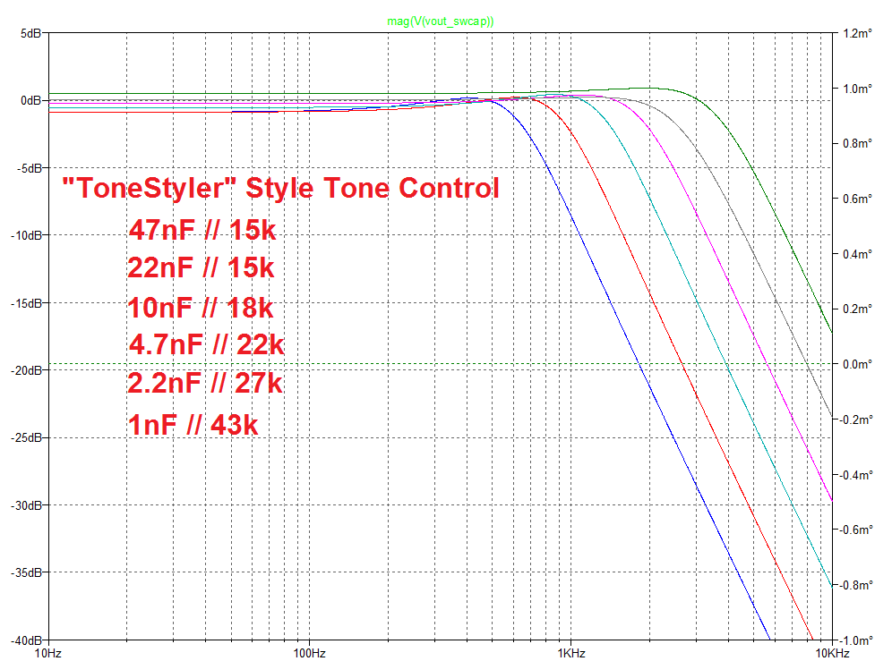
The circuit simulations I show are often "stepped" simply for clarity. You would not be able to make any sense out of an infinite number of overlapping curves after all. But the results I most recently showed for the traditional tone control and the active low pass filter were for circuits that can be infinitely swept by adjusting a pot. When I look at ToneStyler's curves I see a critically damped response unlike the one you get when you just switch in one of several different capacitor values without any pot connected. And indeed in some of their product photos I see a resistor partially hidden behind the switch. So evidently they intentionally damp their circuit with a series or parallel resistance to eliminate the mid band peak that you get without a damping resistor. Some of us like that peak and the "Alembic" state variable filters can produce it too, but many do not like that peak. In my experiments a parallel resistance is more effective than a series resistance in damping the peak and below I show some curves for a switched capacitor tone control (this one really is stepped) with a resistor in parallel with each of the six capacitors. Every capacitor value wants a different resistor to get roughly the same damping but since you are already switching the caps, the switched resistors in parallel just come along for the ride. This is as close as I can come to the OP's request with a passive circuit and there is no easy way to do this in a continuously variable fashion.
If you want to get into circuit simulation you can go to Linear Technology's website and download a free copy of LTSpice, my weapon of choice for pretty much all my general simulation work these days. I have the excellent RF design package, ADS, at work but it does not do much good for audio work. Playing around with circuits on the computer will help a lot to connect theory with practice for you. If you want information on specific topics web searches will generally get you useful stuff. I don't really know any current books that I could recommend and all the ones I do know are long out of print. Your college bookstore will have good general circuit design texts and they may have some more specialized books that cover exactly the topics you are interested in. Semiconductor company web sites often have good tutorial information in application notes if you search around for them.
The circuit simulations I show are often "stepped" simply for clarity. You would not be able to make any sense out of an infinite number of overlapping curves after all. But the results I most recently showed for the traditional tone control and the active low pass filter were for circuits that can be infinitely swept by adjusting a pot. When I look at ToneStyler's curves I see a critically damped response unlike the one you get when you just switch in one of several different capacitor values without any pot connected. And indeed in some of their product photos I see a resistor partially hidden behind the switch. So evidently they intentionally damp their circuit with a series or parallel resistance to eliminate the mid band peak that you get without a damping resistor. Some of us like that peak and the "Alembic" state variable filters can produce it too, but many do not like that peak. In my experiments a parallel resistance is more effective than a series resistance in damping the peak and below I show some curves for a switched capacitor tone control (this one really is stepped) with a resistor in parallel with each of the six capacitors. Every capacitor value wants a different resistor to get roughly the same damping but since you are already switching the caps, the switched resistors in parallel just come along for the ride. This is as close as I can come to the OP's request with a passive circuit and there is no easy way to do this in a continuously variable fashion.
I remember the day I walked out of college with my EE degree and into my first employer's facility. I was scared to death because although my college training had taught me a whole lot of stuff, the one thing they never taught me was what I would actually be doing once I got a job as an engineer! Figuring out how to use what I had been taught was my job back then. These days I think that they do a better job of training students for the real world, partly through internship programs.
If you want to get into circuit simulation you can go to Linear Technology's website and download a free copy of LTSpice, my weapon of choice for
pretty much all my general simulation work these days. I have the excellent RF design package, ADS, at work but it does not do much good for audio work. Playing around with circuits on the computer will help a lot to connect theory with practice for you. If you want information on specific topics web searches will generally get you useful stuff. I don't really know any current books that I could recommend and all the ones I do know are long out of print. Your college bookstore will have good general circuit design texts and they may have some more specialized books that cover exactly the topics you are interested in. Semiconductor company web sites often have good tutorial information in application notes if you search around for them.
View attachment 598800
Oh, I've been done with college for a bit now. I mean I guess I could go to the local campus and take a look but usually I just buy textbooks I want on Amazon these days if I need them. I went to grad school thinking I'd get into academia (fat chance). After I got out I worked at software companies as a developer or data analyst and still do. I didn't know what I was doing either, it was tough to find work. I think companies used to be more willing to take new folks and train them--maybe the other side of the internships everywhere coin.
Thanks for the LTSpice recommendation, I'll give that a shot. Back when I was in those circuits courses we used Matlab and I think PSpice? It's been awhile now though so I don't remember anything about PSpice (but Matlab was used a lot in math courses).
Do you know anything about the book "Art of Electronics" by Paul Horowitz? The third edition was just released I guess. I had only heard one recommendation for that before, hence the reason I ask.
That chart's for swapping out caps? That looks like exactly what the guy wanted. I know they make 24 step rotary switches, so it seems like you could get pretty close to a continuous sweep (it's not continuous but I mean for practical purposes, because of the human ear and whatnot). Might be a pain to put together though.
Last edited:

Thanks, I saw that, and I was put off by the dual filter nature of it - LPFs for each pickup. I really want a single LPF for the entire circuit. Is that not adviseable? I have found that having too many options for tone shaping on the bass is, for me, distracting. I don't even like 3-band cut/boost.There is the SEQ which is a cut down EQ01 for those that find the full preamp has to many options.
That looks like exactly what the guy wanted. I know they make 24 step rotary switches, so it seems like you could get pretty close to a continuous sweep (it's not continuous but I mean for practical purposes, because of the human ear and whatnot). Might be a pain to put together though.
Yep, that's what I wanted, but sweepable. The can of worms this has opened!

Yep, that's what I wanted, but sweepable. The can of worms this has opened!
Yeah! Haha.
It sounds like a 24 or 36 position rotary switch would be the closest. Imagine instead of 6 steps between the left-most and right-most curve you have 24 or 36. One step to the next could have a small enough difference as to make it close to "continuous" to our ears.
The only problem is it sounds like you'd need 24-36 different pairs of capacitors and resistors wired into the different switch positions.
Last edited:
The only problem is it sounds like you'd need 24-36 different pairs of capacitors and resistors wired into the different switch positions.
Aye, there's the rub!
Some time back I made an 11 position switched cap tone control for one of my basses. To my ears that was close enough to continuous that I really had a hard time telling one position from those on either side of it. So I think 6 is enough and I doubt that more than 12 is of much use at all. I have recently rewired that tone switch so that I have 5 cap positions and 5 positions with switched resistors to simulate a traditional tone control and a center off/no load position. Mine does not have the damping resistors however, I just let the response peak as much as it naturally does. I think that gives the tone a nice bark to it that is useful sometimes and for other times I can use the traditional tone settings or switch it over to the active 3 band EQ. But to each their own.
Part of the problem with the passive approach is that the response is the result of not only the capacitors and damping resistors but also the pickups and their series resistance. So the details of the response will vary from pickup to pickup and also with how you have the blend or volume controls set on a two pickup bass. The active version will be immune to these influences and that makes it a "safer" choice if you don't want to spend a lot of time tweaking capacitor values.
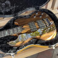
A shelf filter would be fine, as long as the knee is moveable and can go pretty high - like 7K Hz +, so I can get it out of the way. My experience with shelving filters, eg EMG and pretty much every active filter on the market except for a para-mid, is that way - the frequency knee is preset, and the amount of shelving, therefore the slope of the curve, varies. I'm looking to preset the slope/amount of cut and move the frequency.
It occurred to me that I could probably get something similar to this with something like a 5-way switch and various caps, but not exactly what i'm after.
thanks,
Are you pretty much describing Alembic Series II electronics?
don't know, but if I am, have a look at what it might cost, if I could even get it.Are you pretty much describing Alembic Series II electronics?
[Invalid or Expired Link Removed]
I have to say that the SEQ looks tempting; however, a couple of things put me off: Being ham-fisted (I think my fingers were initially intended to all be big toes), the stacked volume/blend gives me trouble. And while I'm certain the filters for each pickup are useful, it's more than what I want. I just want volume/blend/filter for the whole circuit. The basses the control will go into has a very small cavity (think P-Bass), so less is more.There is the SEQ which is a cut down EQ01 for those that find the full preamp has to many options.
I have to congratulate ACG for the tidiness of those electronics. Man, it looks nice.
You need to find an EQ02 then and just unplug the high pass filter. But I doubt it would fit in such a small cavity.
Thanks, but as they are no longer made... and whopping expensive...You need to find an EQ02 then and just unplug the high pass filter. But I doubt it would fit in such a small cavity.
Yes discontinued because to get the best from a filter system you need one filter per pickup which is why most have that feature. Look at the price of an Alembic system and the price is pretty good. The price is inline with top end preamps made in Europe so we will have to disagree regarding the pricing.
Saying this all with much respect, I'm not sure I understand how the ACG filters work - they filter out the high end, being low pass... so they have a fixed slope? and the frequency knob adjusts where the slope acts in the frequency range? If so, I don't understand the specs saying that the filter's upper frequency is 3.5K. in my head, that means it will start to filter out high frequencies at 3.5K. that seems low, if what I have in my head is the way it is. I am probably wrong, feel free to berate...Yes discontinued because to get the best from a filter system you need one filter per pickup which is why most have that feature. Look at the price of an Alembic system and the price is pretty good. The price is inline with top end preamps made in Europe so we will have to disagree regarding the pricing.
A graph would be much useful.
The lower ring adjusts the filter cut off point. The filter range is from 70 hz to 3.5khz. Fully open it lets through around 3.5khz nothing beyond that point. The pre-amp also has a sub filter to removed sub sonic frequencies in order to stop the amp and cab trying to reproduce stuff that is no use and soaks up a lot of power. The filter range relates to what we feel is useful for a bass guitar. The Alembic goes higher the Wal stops at 3k. The Alembic goes down to 250hz the Wal down to 70 hz it is a choice. If you make the filter with a large range adjusting the cut off becomes very difficult with a small rotation of the pot leading to a large change in the sound. This is the reason we reduced the lowpass filter range on the DFM to make it more useable. As far as the filter in my own pre-amp cutting off at 3.5khz there is a high pass filter that works up to 8khz in the EQ01 and on the DFM the sweepable mid/treble goes up to 5khz so the full range is covered. Personally I find the lowpass filter 70/3.5 more than enough to achieve what I want from a bass the option to go beyond that in both pre-amps is there if needed. I don't have a graph and my technical knowledge is limited that is why I get John East to do all the clever stuff for me.
As it turns out you can do this with a single opamp fairly well. The well known Sallen Key topology can give you a nice sweepable cutoff if you use two pot elements as shown that are ganged on a single shaft. The schematic is not complete, you would use the other half of a dual opamp to make an input buffer to raise the input impedance. The filter is not quite as well controlled as the state variable based designs but it appears like it would work well and it takes half the battery current. Also not shown in this schematic are the biasing components or rather they are shown as voltage sources.
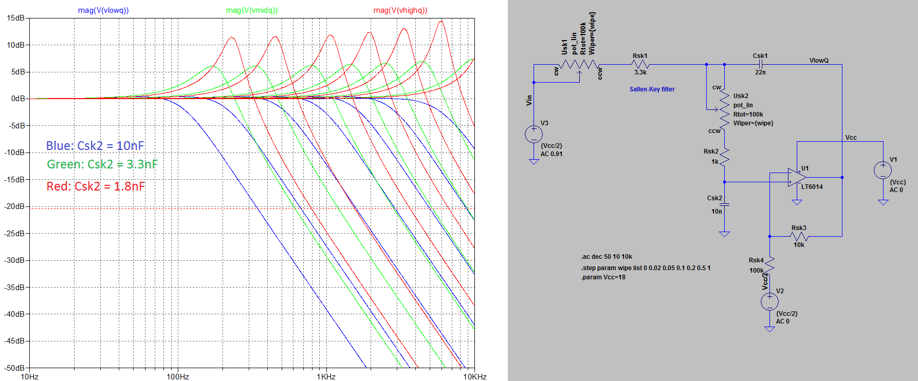
Ha, looks like Mr Hutch beat me to the punch, but I'll post mine anyway.
I used the same filter, but cascaded two of them after I saw these on ebay. I figured, hey, if you're gonna go active, may as well use a 4th order to really get that "brick wall" treble cut. (Although the state variable filter is only a 2nd order.)
You can still use a dual opamp if you buffer with a simple npn transistor. Lots of the old boss pedals use exactly this same buffer.
The opamp is your choice. Any of the common audio ones will be fine. A TL062 will give very good battery life, and in a "treble cut" circuit, the higher noise won't be an issue.
As it is, the caps give just a little resonant peak. About 4dB - between khutch's green and blue lines. If you keep the mean capacitance, but increase the ratio of the small to large cap, that peak will go up without changing the sweep range. (Which is 100Hz to 10Khz, BTW.)
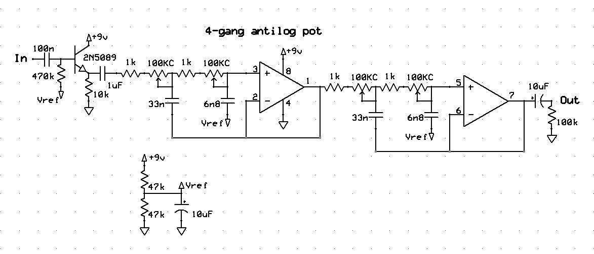
It's definitely worth trying one onboard, but I think it would be really cool to try this after a fuzz pedal. Although perhaps with a little more resonance. 47n and 4n7 will give a 9dB resonant peak. 68n and 3n3 will give a 15dB peak etc etc...
If you ask nicely, I might even put a stripboard layout together...
I used the same filter, but cascaded two of them after I saw these on ebay. I figured, hey, if you're gonna go active, may as well use a 4th order to really get that "brick wall" treble cut. (Although the state variable filter is only a 2nd order.)
You can still use a dual opamp if you buffer with a simple npn transistor. Lots of the old boss pedals use exactly this same buffer.
The opamp is your choice. Any of the common audio ones will be fine. A TL062 will give very good battery life, and in a "treble cut" circuit, the higher noise won't be an issue.
As it is, the caps give just a little resonant peak. About 4dB - between khutch's green and blue lines. If you keep the mean capacitance, but increase the ratio of the small to large cap, that peak will go up without changing the sweep range. (Which is 100Hz to 10Khz, BTW.)
It's definitely worth trying one onboard, but I think it would be really cool to try this after a fuzz pedal. Although perhaps with a little more resonance. 47n and 4n7 will give a 9dB resonant peak. 68n and 3n3 will give a 15dB peak etc etc...
If you ask nicely, I might even put a stripboard layout together...
Last edited:
nicely...Ha, looks like Mr Hutch beat me to the punch, but I'll post mine anyway.
I used the same filter, but cascaded two of them after I saw these on ebay. I figured, hey, if you're gonna go active, may as well use a 4th order to really get that "brick wall" treble cut. (Although the state variable filter is only a 2nd order.)
You can still use a dual opamp if you buffer with a simple npn transistor. Lots of the old boss pedals use exactly this same buffer.
The opamp is your choice. Any of the common audio ones will be fine. A TL062 will give very good battery life, and in a "treble cut" circuit, the higher noise won't be an issue.
As it is, the caps give just a little resonant peak. About 4dB - between khutch's green and blue lines. If you keep the mean capacitance, but increase the ratio of the small to large cap, that peak will go up without changing the sweep range. (Which is 100Hz to 10Khz, BTW.)
View attachment 599903
It's definitely worth trying one onboard, but I think it would be really cool to try this after a fuzz pedal. Although perhaps with a little more resonance. 47n and 4n7 will give a 9dB resonant peak. 68n and 3n3 will give a 15dB peak etc etc...
If you ask nicely, I might even put a stripboard layout together...
edit: and you know, I hadn't thought of using on fuzz or distortion as I don't use them. but, the "brick wall" (very apt name) would, for me at least, make those effects much more useful. if it's anything I hate, it's buzzy bass.
Latest posts
-
-
Software drums recommendation for practice Latin, Cumbia styles preferred
- Latest: bass player 53
-

-

