
Enjoy the benefits of a premium membership!
Upgrade Account
-
TalkBass has been independent since 1998. Add your voice.
Create a free account to reply to discussions, view embedded media, and browse with fewer display ads.
Join free Log in
Want zero display ads or expanded classifieds tools? Compare plans.
You are using an out of date browser. It may not display this or other websites correctly.
You should upgrade or use an alternative browser.
You should upgrade or use an alternative browser.
A short scale 4-string headless
- Thread starter Dave Higham
- Start date
More options
Who Replied?

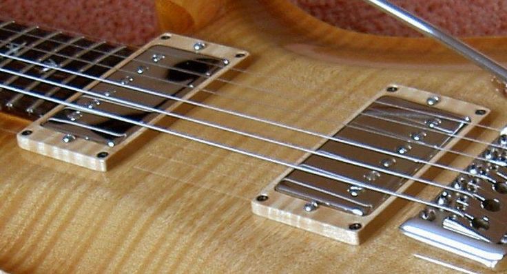

Thank you for your sympathy and suggestions. A ramp or a thumb rest are good suggestions and I might resort to something like that in the end, but as I think I mentioned, this is a sort of retrospective build thread and this happened about 5 weeks ago. So this is what I did next.
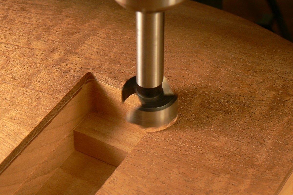
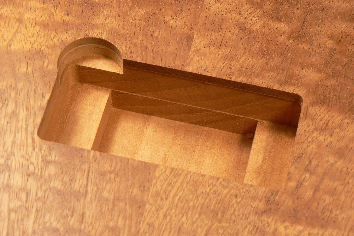
Even though my down-cut router cutter gave me a nice clean edge there's no way I could make a piece to glue in there that wouldn't stand out like a sore thumb. So I decided that I'd have to alter the shape to one I'd have a better chance of repairing, i.e. circular. The biggest Forstner bit I had was 26 mm diameter which would just cover the damage and with a bit of luck I should be able to turn a plug to be a perfect fit in the hole. So I altered the shape.
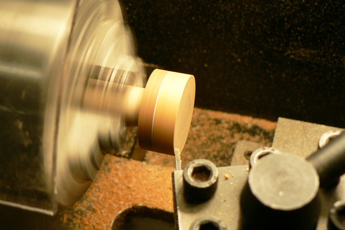
I made a sandwich of the piece of drop top that came out of the pickup cut-out (which already had white veneer glued to it) and an off-cut of the body and turned a plug.
I also used the Forstner bit to cut a hole in another drop top off-cut to use as a test piece for the plug diameter.
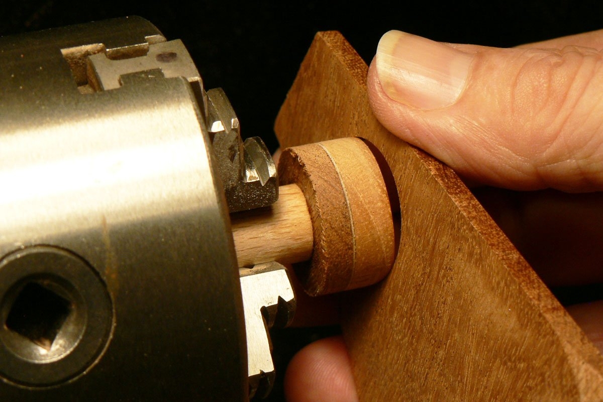
This looks about right. It's a tight fit but it needs to be.
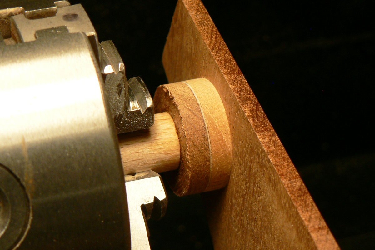
Trying it in the body. The plug is slightly thicker than the depth of the hole so I can skim it flush when it's glued in.
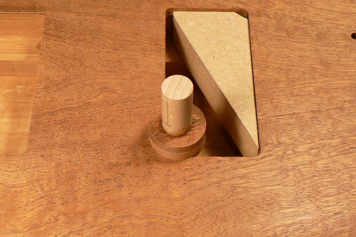
Although the hole is a bit more than a semi-circle, I think the plug might need some help staying in place so I made a couple of little wedges to force it into contact.
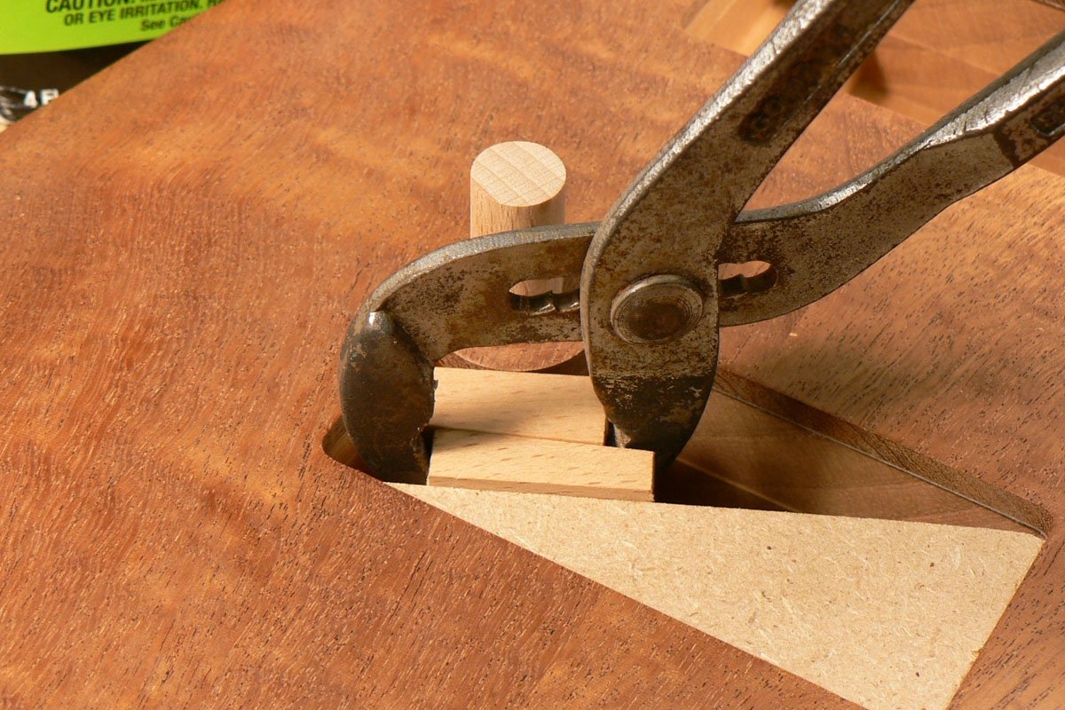
So then I glued it in. Sorry about the fuzzy photo.

Even though my down-cut router cutter gave me a nice clean edge there's no way I could make a piece to glue in there that wouldn't stand out like a sore thumb. So I decided that I'd have to alter the shape to one I'd have a better chance of repairing, i.e. circular. The biggest Forstner bit I had was 26 mm diameter which would just cover the damage and with a bit of luck I should be able to turn a plug to be a perfect fit in the hole. So I altered the shape.
I made a sandwich of the piece of drop top that came out of the pickup cut-out (which already had white veneer glued to it) and an off-cut of the body and turned a plug.
I also used the Forstner bit to cut a hole in another drop top off-cut to use as a test piece for the plug diameter.
This looks about right. It's a tight fit but it needs to be.
Trying it in the body. The plug is slightly thicker than the depth of the hole so I can skim it flush when it's glued in.
Although the hole is a bit more than a semi-circle, I think the plug might need some help staying in place so I made a couple of little wedges to force it into contact.
So then I glued it in. Sorry about the fuzzy photo.

I’ll try to be helpful to make up for being a smart aleck earlier. 
Sine this is a recap you’ve probably already done the finish but one thing I got from Dan Earlewine that I’ve done and seemed to help is to use an Xacto and carve some faux grain lines across the glue line of the plug to help break up the outline.
Sine this is a recap you’ve probably already done the finish but one thing I got from Dan Earlewine that I’ve done and seemed to help is to use an Xacto and carve some faux grain lines across the glue line of the plug to help break up the outline.
No Matt, the finish isn't done yet and that's another good suggestion. But here's the next episode.
I left it overnight and the next day skimmed it down flush with the surface. The result was very disappointing. I'd used epoxy to glue it in (I don't really know why) and perhaps this was a mistake because there was a dark brown circular glue line that was shouting "this is where he messed it up"! Perhaps the epoxy soaked into the wood; I don't know, but I decided I'd have to have another go at it (and forgot to take a photo).
So I needed a bigger Forstner bit and the only place I had a chance of getting one in a hurry was Amazon. Like 'em or hate 'em, it was in my post box the next day.
This time I made a sacrificial block which I wedged hard into the corner before using the new Forstner bit, made the plug slightly tapered, put a smear of Titebond around the part of the hole that the plug needed to be glued to and rammed the plug in.
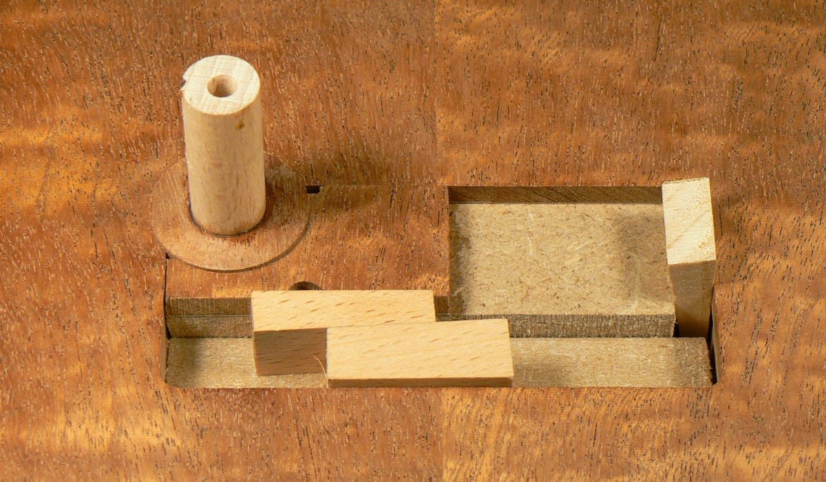
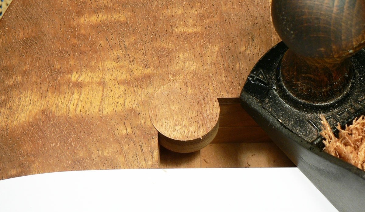
When the glue was dry I took it apart and started skimming it flush and it looked much more promising.
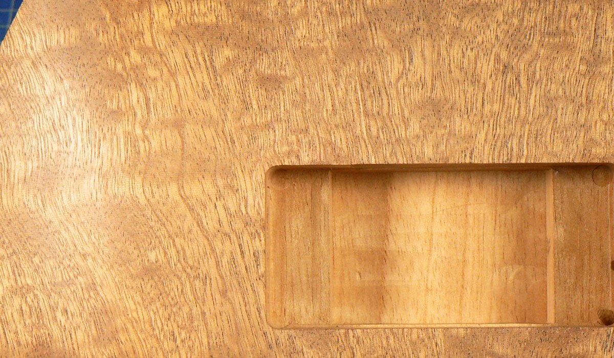
Finally I re-routered the cut-out and this is what it looked like. It's not quite invisible but I don't think you see it if you don't know it's there. Of course I may have a problem when it comes to finishing because I gave it a wipe with alcohol and a very thin line showed up. If anyone knows how to avoid it becoming visible under finish I'm all ears. If it is too noticeable I might go back to the ramp or thumb rest idea.
I left it overnight and the next day skimmed it down flush with the surface. The result was very disappointing. I'd used epoxy to glue it in (I don't really know why) and perhaps this was a mistake because there was a dark brown circular glue line that was shouting "this is where he messed it up"! Perhaps the epoxy soaked into the wood; I don't know, but I decided I'd have to have another go at it (and forgot to take a photo).
So I needed a bigger Forstner bit and the only place I had a chance of getting one in a hurry was Amazon. Like 'em or hate 'em, it was in my post box the next day.
This time I made a sacrificial block which I wedged hard into the corner before using the new Forstner bit, made the plug slightly tapered, put a smear of Titebond around the part of the hole that the plug needed to be glued to and rammed the plug in.
When the glue was dry I took it apart and started skimming it flush and it looked much more promising.
Finally I re-routered the cut-out and this is what it looked like. It's not quite invisible but I don't think you see it if you don't know it's there. Of course I may have a problem when it comes to finishing because I gave it a wipe with alcohol and a very thin line showed up. If anyone knows how to avoid it becoming visible under finish I'm all ears. If it is too noticeable I might go back to the ramp or thumb rest idea.



Well it's perfectNo Matt, the finish isn't done yet and that's another good suggestion. But here's the next episode.
I left it overnight and the next day skimmed it down flush with the surface. The result was very disappointing. I'd used epoxy to glue it in (I don't really know why) and perhaps this was a mistake because there was a dark brown circular glue line that was shouting "this is where he messed it up"! Perhaps the epoxy soaked into the wood; I don't know, but I decided I'd have to have another go at it (and forgot to take a photo).
So I needed a bigger Forstner bit and the only place I had a chance of getting one in a hurry was Amazon. Like 'em or hate 'em, it was in my post box the next day.
This time I made a sacrificial block which I wedged hard into the corner before using the new Forstner bit, made the plug slightly tapered, put a smear of Titebond around the part of the hole that the plug needed to be glued to and rammed the plug in.
View attachment 7194229
When the glue was dry I took it apart and started skimming it flush and it looked much more promising.
View attachment 7194230
Finally I re-routered the cut-out and this is what it looked like. It's not quite invisible but I don't think you see it if you don't know it's there. Of course I may have a problem when it comes to finishing because I gave it a wipe with alcohol and a very thin line showed up. If anyone knows how to avoid it becoming visible under finish I'm all ears. If it is too noticeable I might go back to the ramp or thumb rest idea.
View attachment 7194232
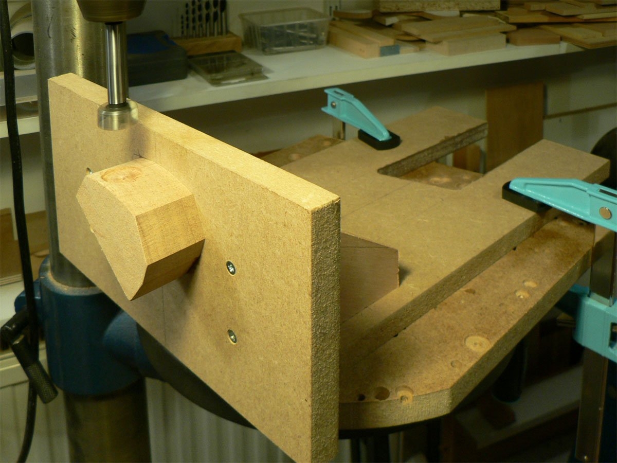
I fit Electrosockets to my instruments which means shaping a block of wood to fit inside the control cavity and attaching it to this contraption.
Then fitting the body onto it and drilling the holes.
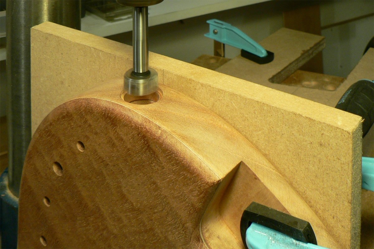
Then fitting the body onto it and drilling the holes.
I now need to route the neck pocket, for which I'll need a template and to make a template I'll need a neck.
I keep having senior moments where photos are concerned and realise I haven't taken any.
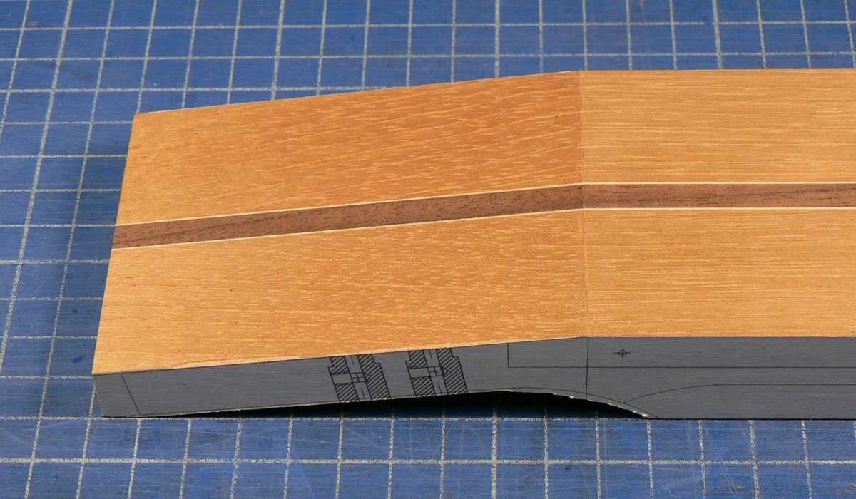
So I got a cedar neck blank, cut it in half down the middle, flipped one half end-to-end and glued it back together with a walnut stringer and two maple veneers. Although it's a headless, it does have a sort of headstock, so I band-sawed a bit off the front and back and planed the front of the 'headstock' smooth
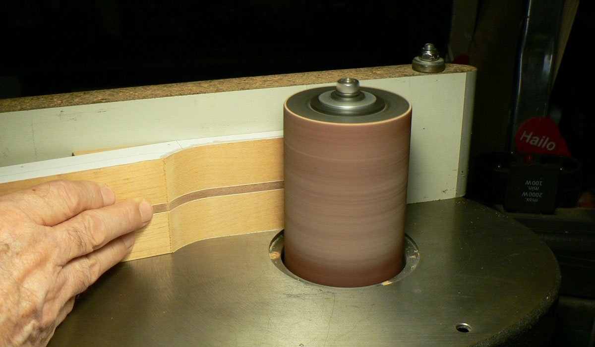
Then sanded the back to finish at 16 mm (about 5/8") thick.
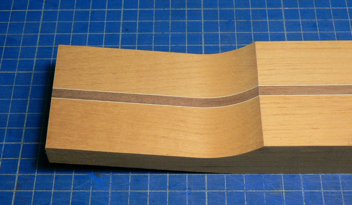
I keep having senior moments where photos are concerned and realise I haven't taken any.
So I got a cedar neck blank, cut it in half down the middle, flipped one half end-to-end and glued it back together with a walnut stringer and two maple veneers. Although it's a headless, it does have a sort of headstock, so I band-sawed a bit off the front and back and planed the front of the 'headstock' smooth
Then sanded the back to finish at 16 mm (about 5/8") thick.
I drilled 5 mm holes where the string anchors will be (no photos) and then set up to cut channels for the carbon fibre rods. I spent some time working out where to put the stops for the channels. The stops are the three bits of wood attached with double sided tape, two to the rudimentary fence, and one to the neck blank.
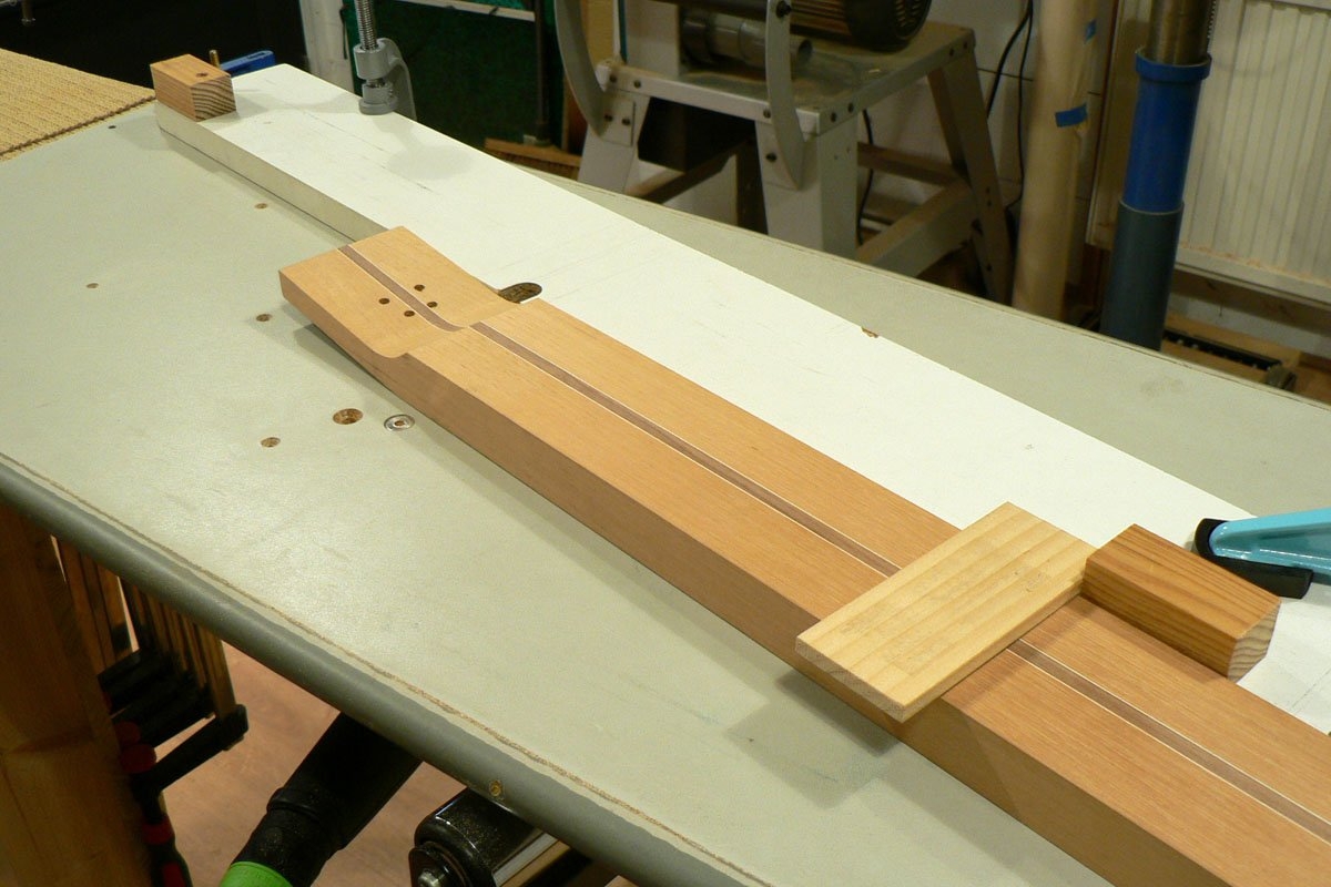
Channels cut.
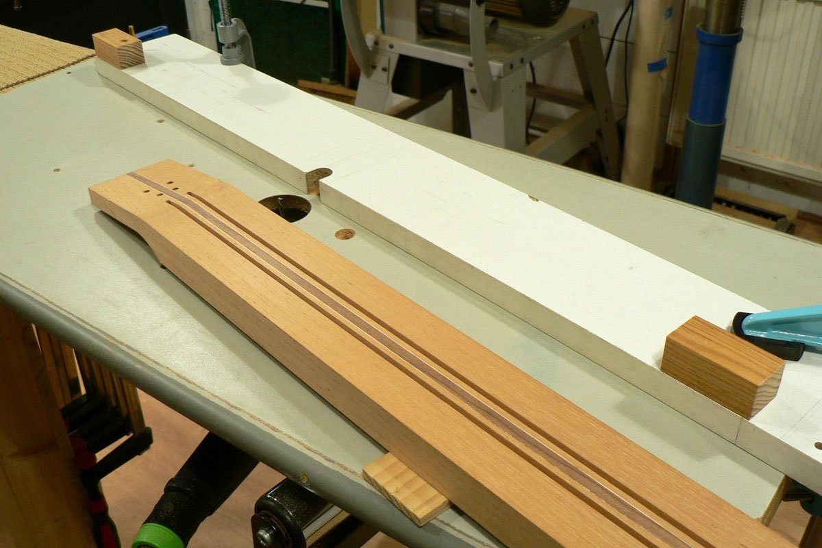
The CF rods were a nice snug fit in the channels so I wicked water-thin CA down both sides of them, at the same time pushing them hard down into the channels.
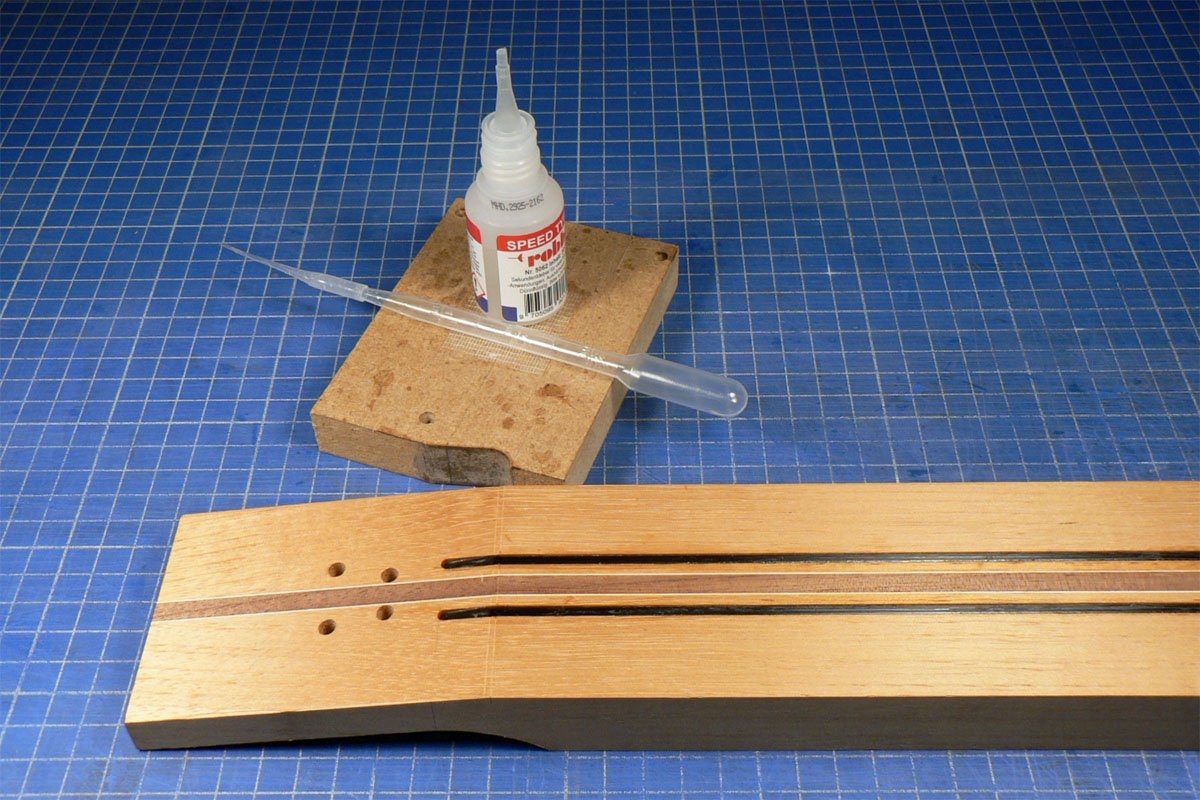
I then routed the channel for the truss rod.
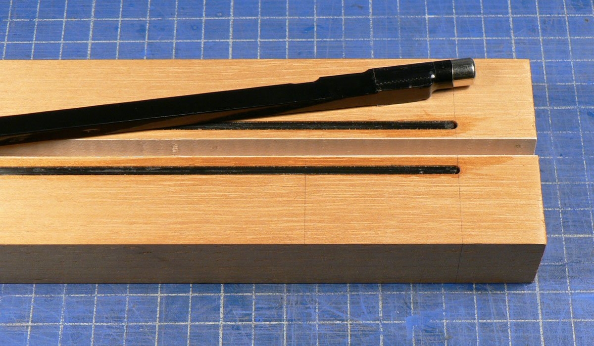
Channels cut.
The CF rods were a nice snug fit in the channels so I wicked water-thin CA down both sides of them, at the same time pushing them hard down into the channels.
I then routed the channel for the truss rod.
The business end of the truss rod is a bit wider so I widened the channel in that area on the milling machine.
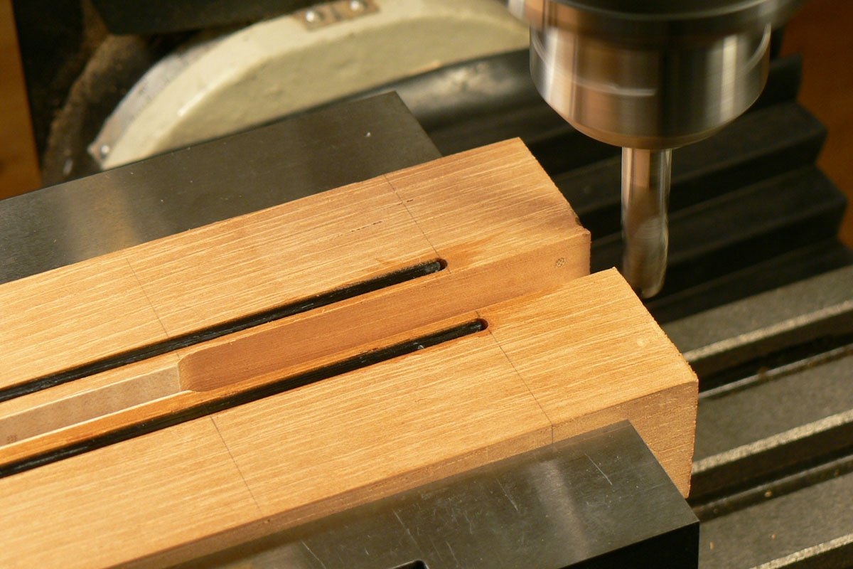
I made a little piece of wood to go in that area . . .
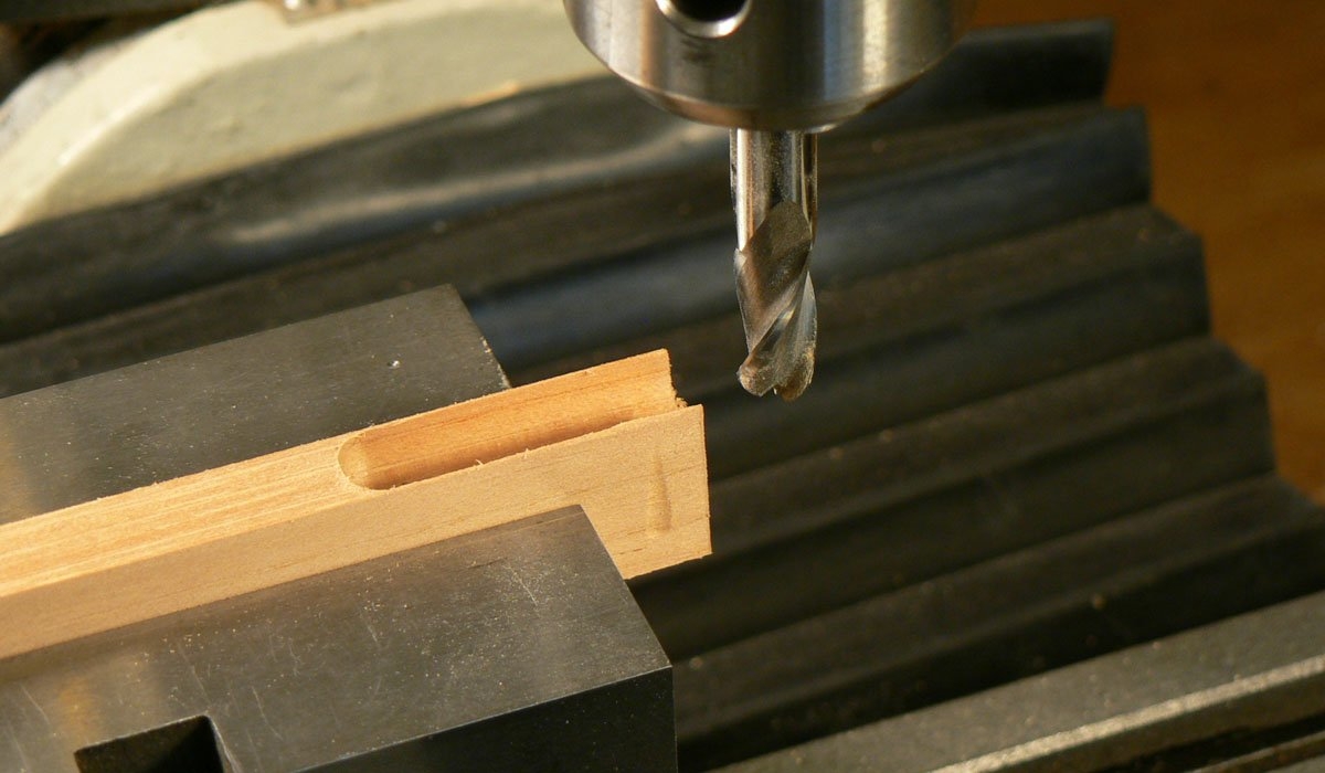
. . . and a filler strip for the rest of the channel.
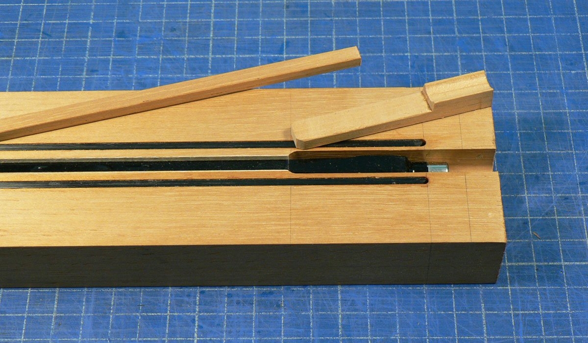
Glued them in . . .
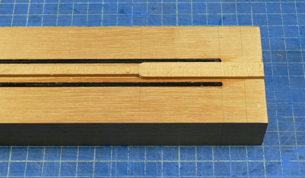
. . . and skimmed them flush.
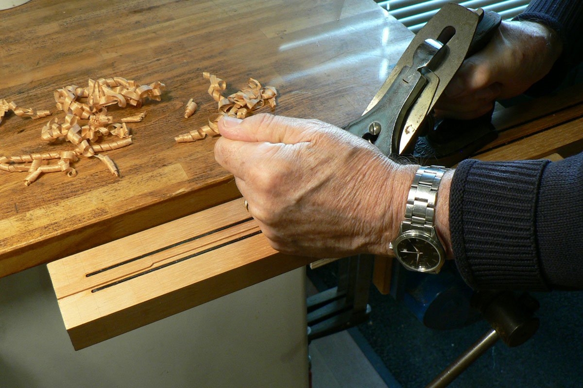
I made a little piece of wood to go in that area . . .
. . . and a filler strip for the rest of the channel.
Glued them in . . .
. . . and skimmed them flush.

- Apr 18, 2008
- 16,008
- 1
- 31,707
- Disclosures
- I'm highly opinionated and extremely self-assured
 My ocd approves of this thread.
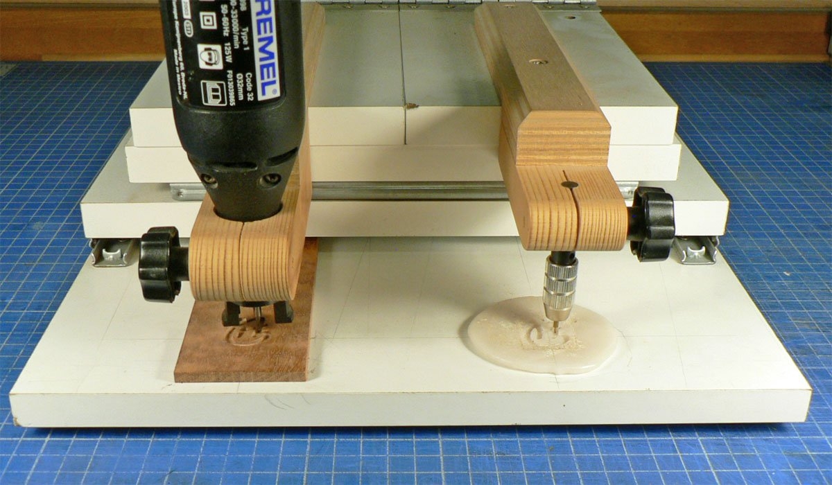
I made a headstock veneer from another off-cut of the drop top. It gets engraved for the MOP logo before being thinned down to 1.5 mm (1/16")
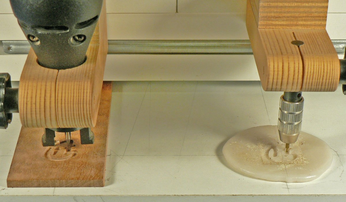
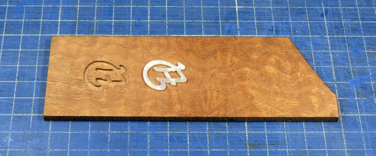
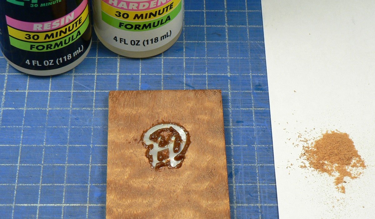
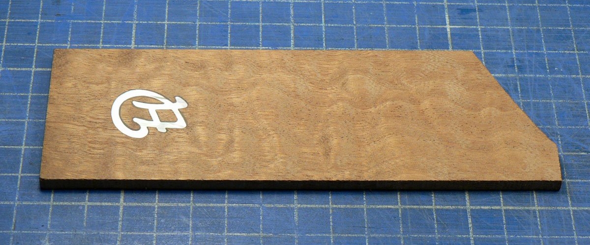
Gluing a backstrap veneer
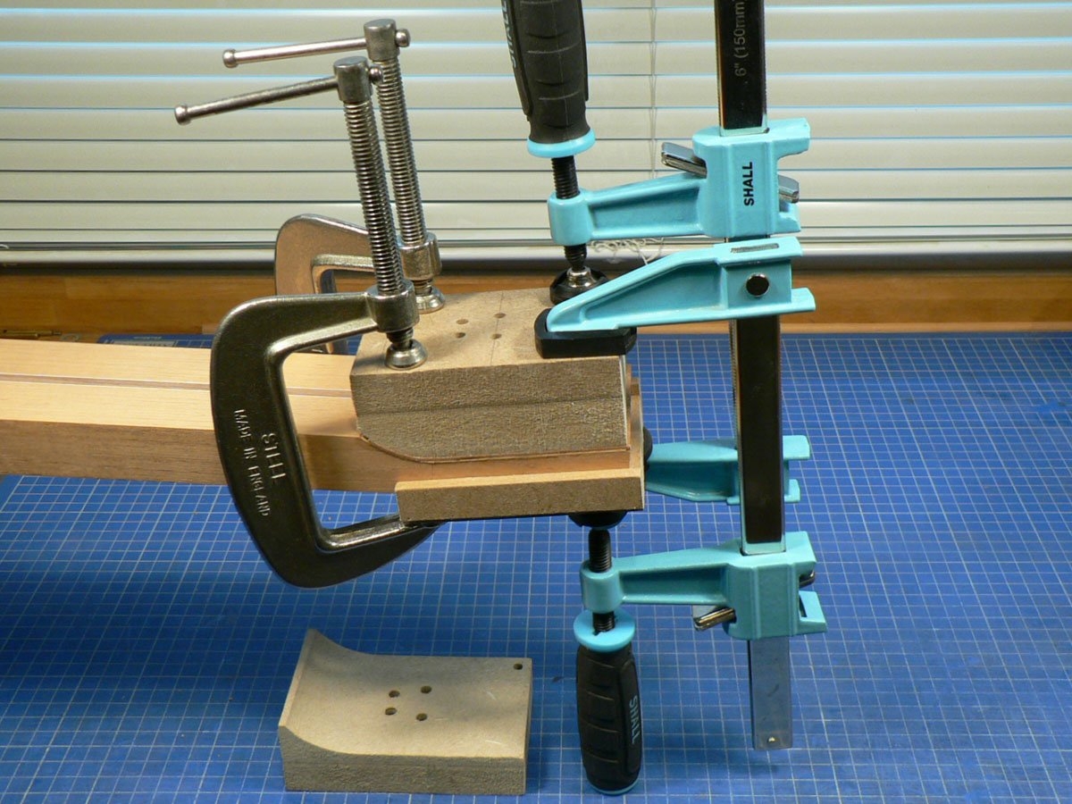
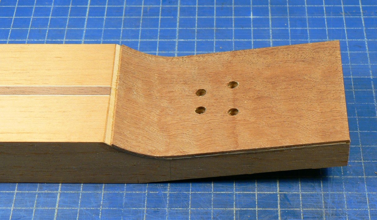
The front veneer glued on.
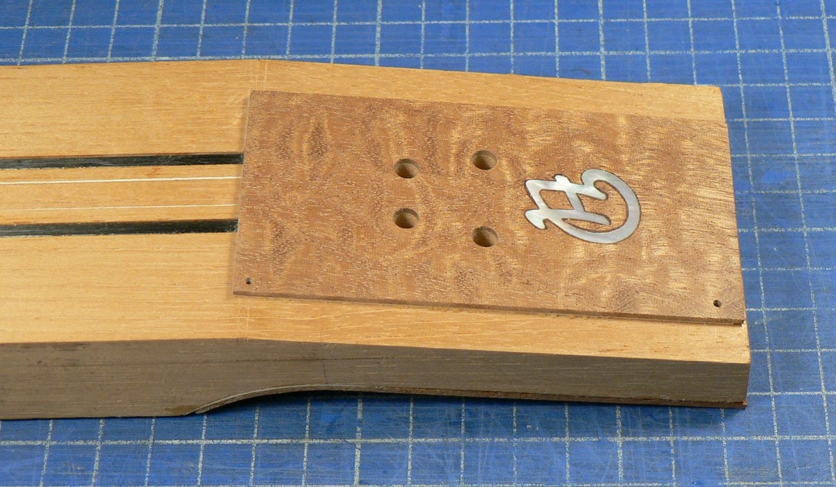
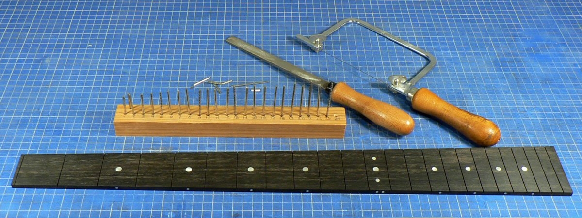
Made an ebony fret board, fitted pearl dots and cut the frets and forgot about taking photos.
Having made the fret board I used it as a template to cut the neck blank to size, but there aren't any photos of that either. Sorry.
The front veneer glued on.
Made an ebony fret board, fitted pearl dots and cut the frets and forgot about taking photos.
Having made the fret board I used it as a template to cut the neck blank to size, but there aren't any photos of that either. Sorry.
When I drilled the 5 mm holes in the headstock I made a template as, before they become string anchor holes, they serve as dowel holes for positioning the headstock and backstrap veneers, etc.
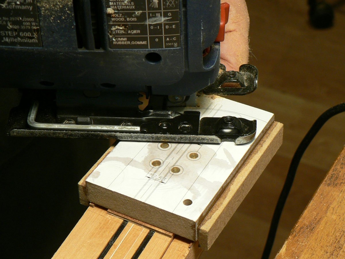
This is the template attached with dowels, being cut together with the headstock to its final shape. The fifth hole is for a dowel used as a pivot to sand the curve at the end.
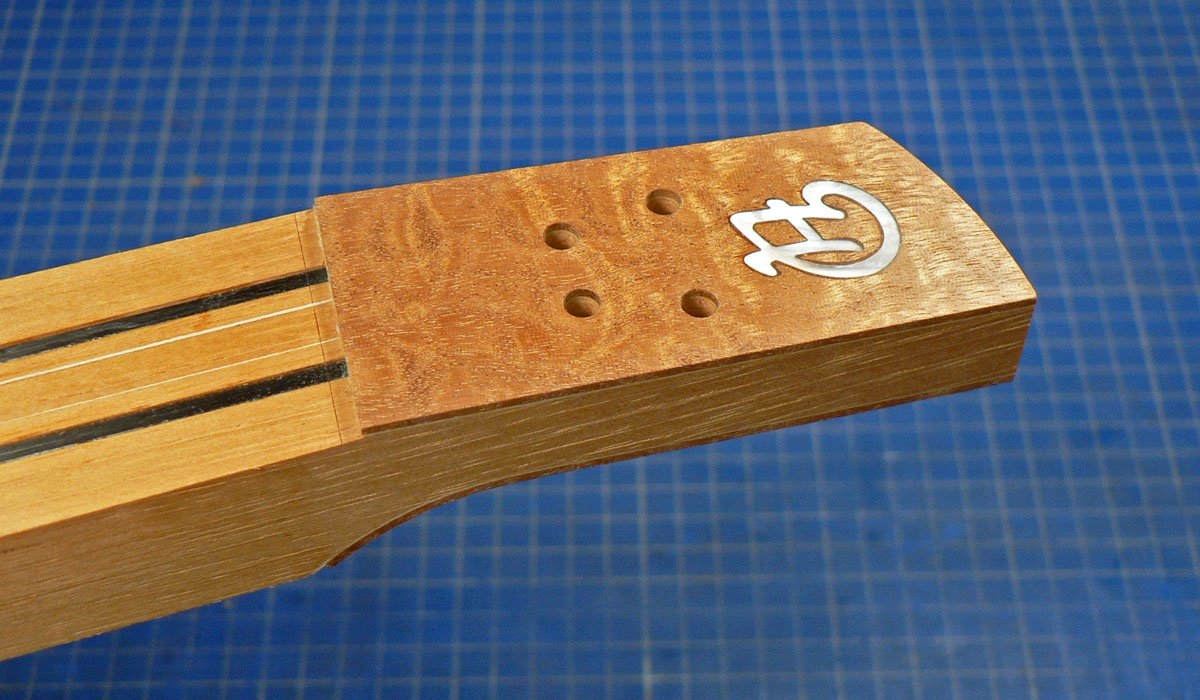
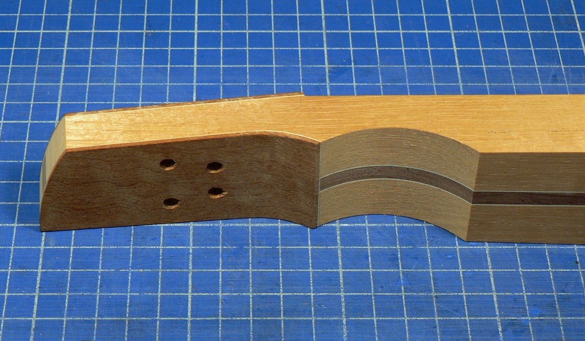
So this is what the ‘headstock’ looks like. Seen from the front it’s just a continuation of the neck but slopes back at 7.5°. It’s not a very steep angle, but as the strings don’t go to tuners the break angle will be more than that of a Fender E string.
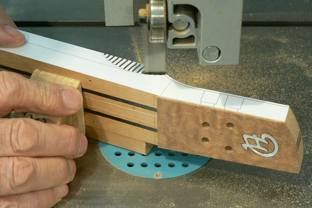
Starting to cut the neck down to finished thickness.
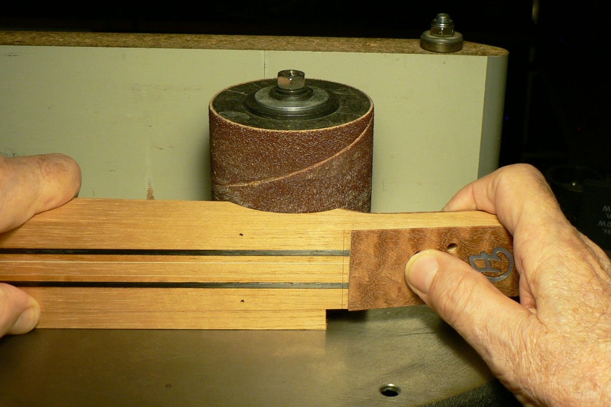
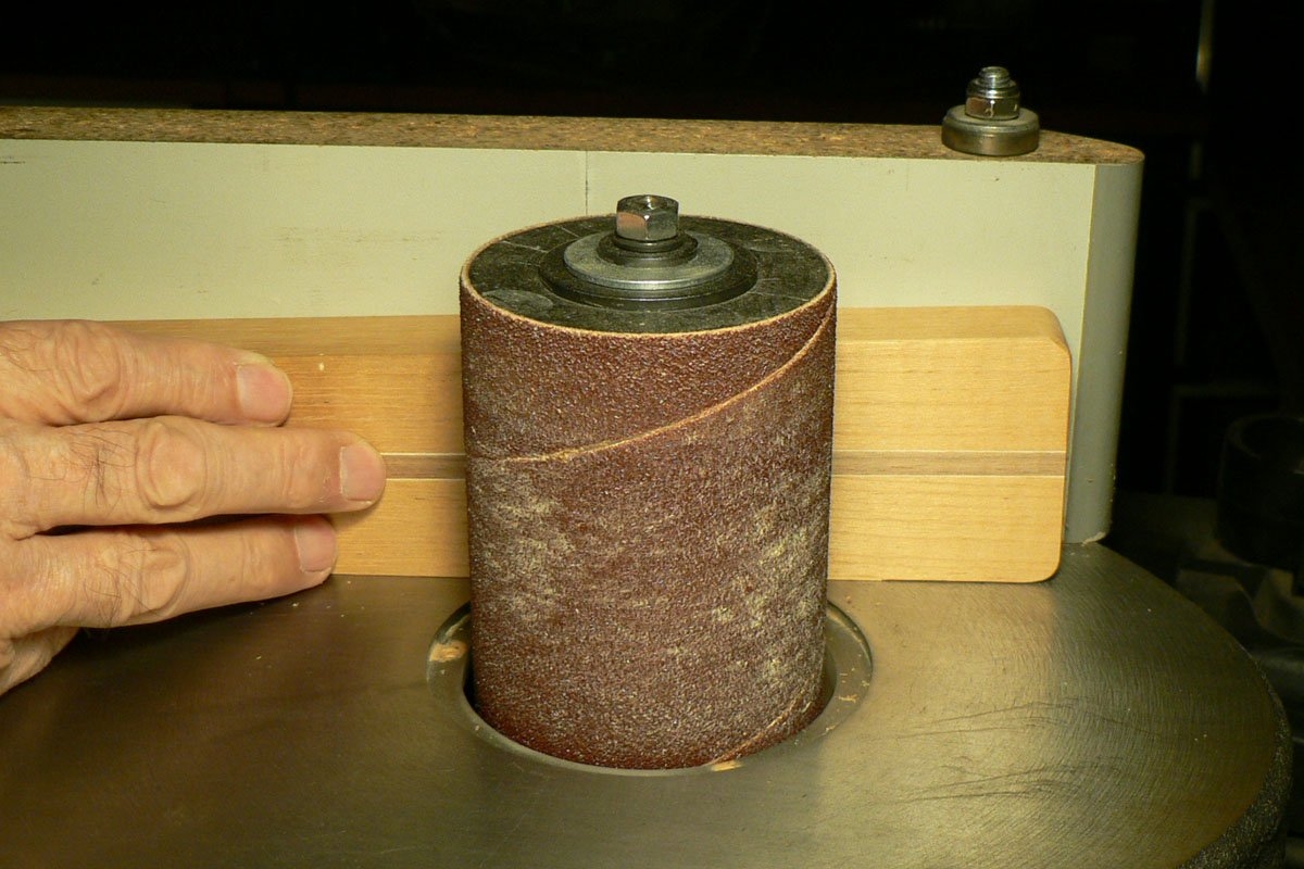
Finishing the volute on the sander.
Taking the heel down to finished thickness. Most of the extra thickness was taken off on the band saw and finished on the sander.
This is the template attached with dowels, being cut together with the headstock to its final shape. The fifth hole is for a dowel used as a pivot to sand the curve at the end.
So this is what the ‘headstock’ looks like. Seen from the front it’s just a continuation of the neck but slopes back at 7.5°. It’s not a very steep angle, but as the strings don’t go to tuners the break angle will be more than that of a Fender E string.
Starting to cut the neck down to finished thickness.
Finishing the volute on the sander.
Taking the heel down to finished thickness. Most of the extra thickness was taken off on the band saw and finished on the sander.
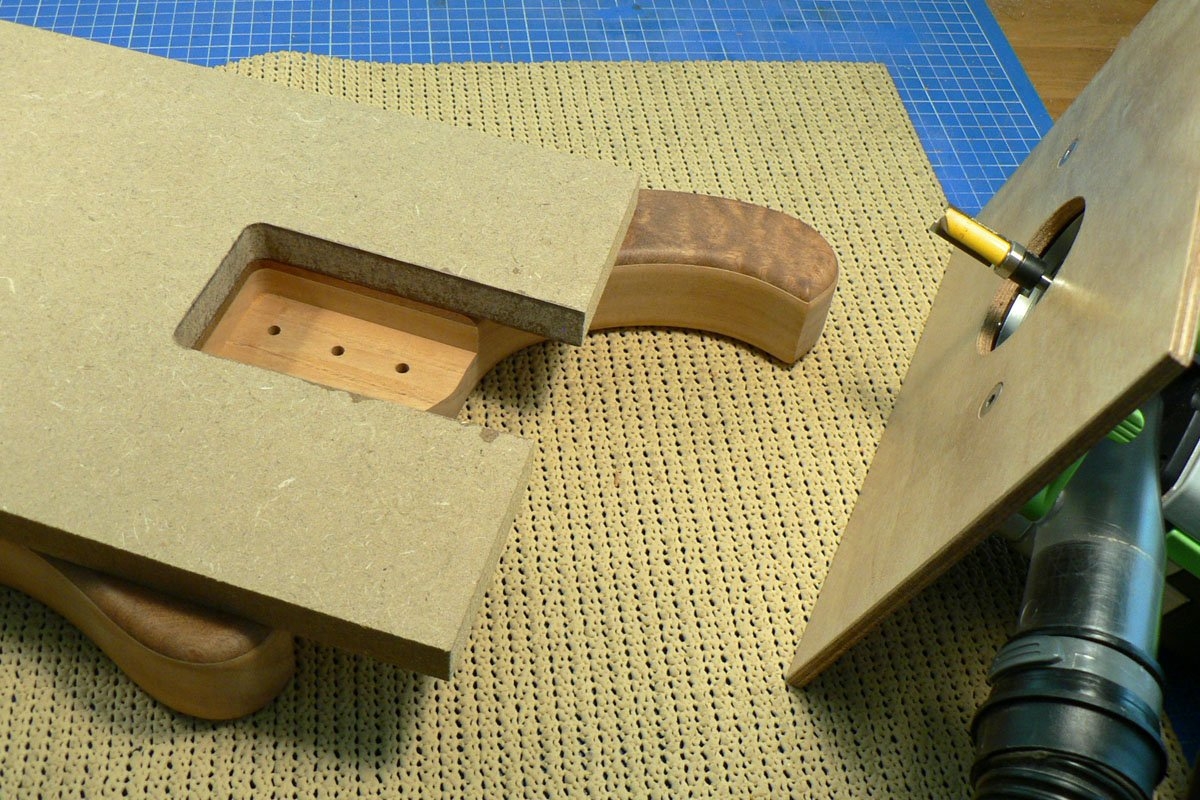
So then I pinned the fingerboard to the neck using panel pins through two of the fret slots and trimmed the neck flush with the fingerboard by taking the bulk off on the band saw and finishing on the router table. Then took the f’board off again and used the neck to make a routing template for the neck pocket in the body.
And guess what? Yes, I forgot to take photos. It must be my age. Although if you’ve seen my other build threads you’ve seen it all before.
But here’s a photo of the neck pocket with the template. . .
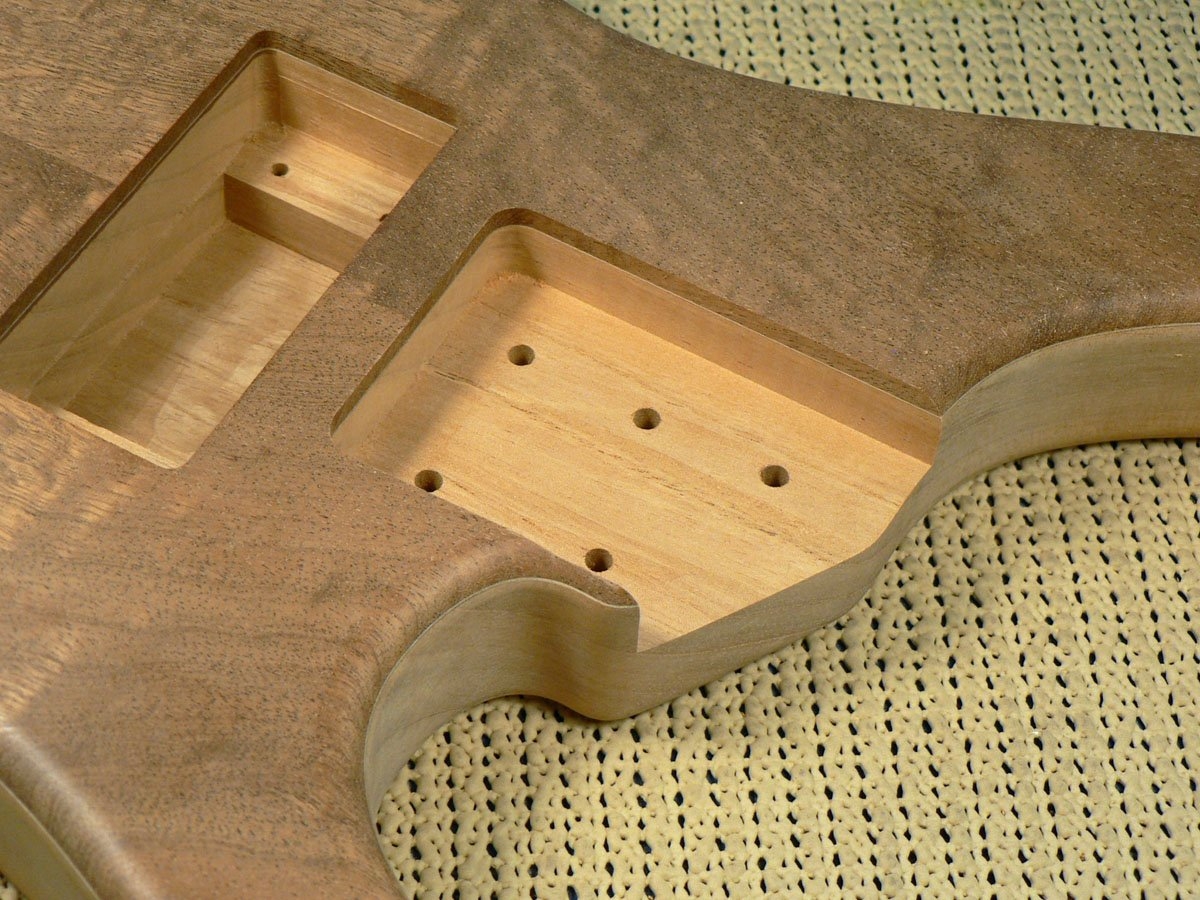
. . . and without it.
And guess what? Yes, I forgot to take photos. It must be my age. Although if you’ve seen my other build threads you’ve seen it all before.
But here’s a photo of the neck pocket with the template. . .
. . . and without it.
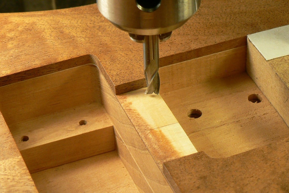
I need access to the truss rod, so I milled out an area between the neck pocket and the neck pickup cavity.
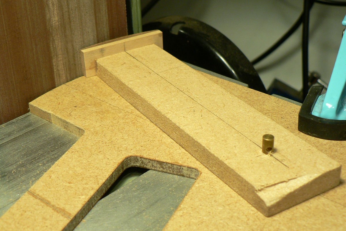
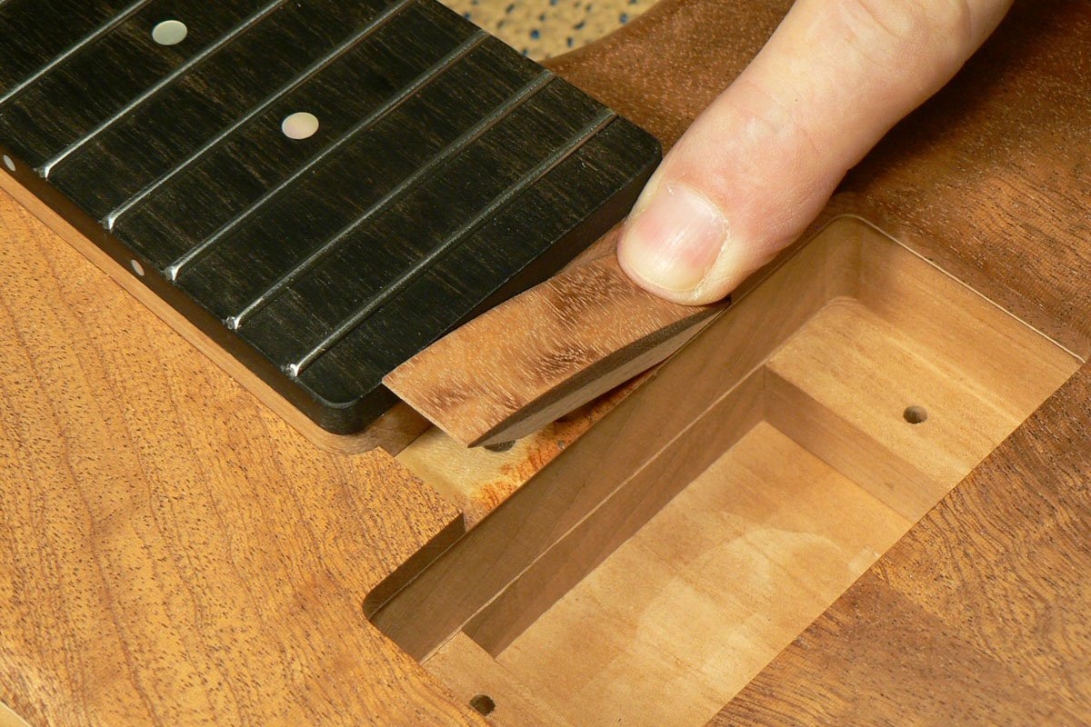
As I’ve mentioned in another thread, I didn’t want to recess the bridge/tuners into the body or angle the neck, so the neck protrudes more than ‘usual’ out of the body. This means that if the truss rod cover plate is flush with the body it doesn’t quite cover the truss rod hole. So I made a convex cover plate and rigged up this makeshift jig to sand a curve onto the top of it.
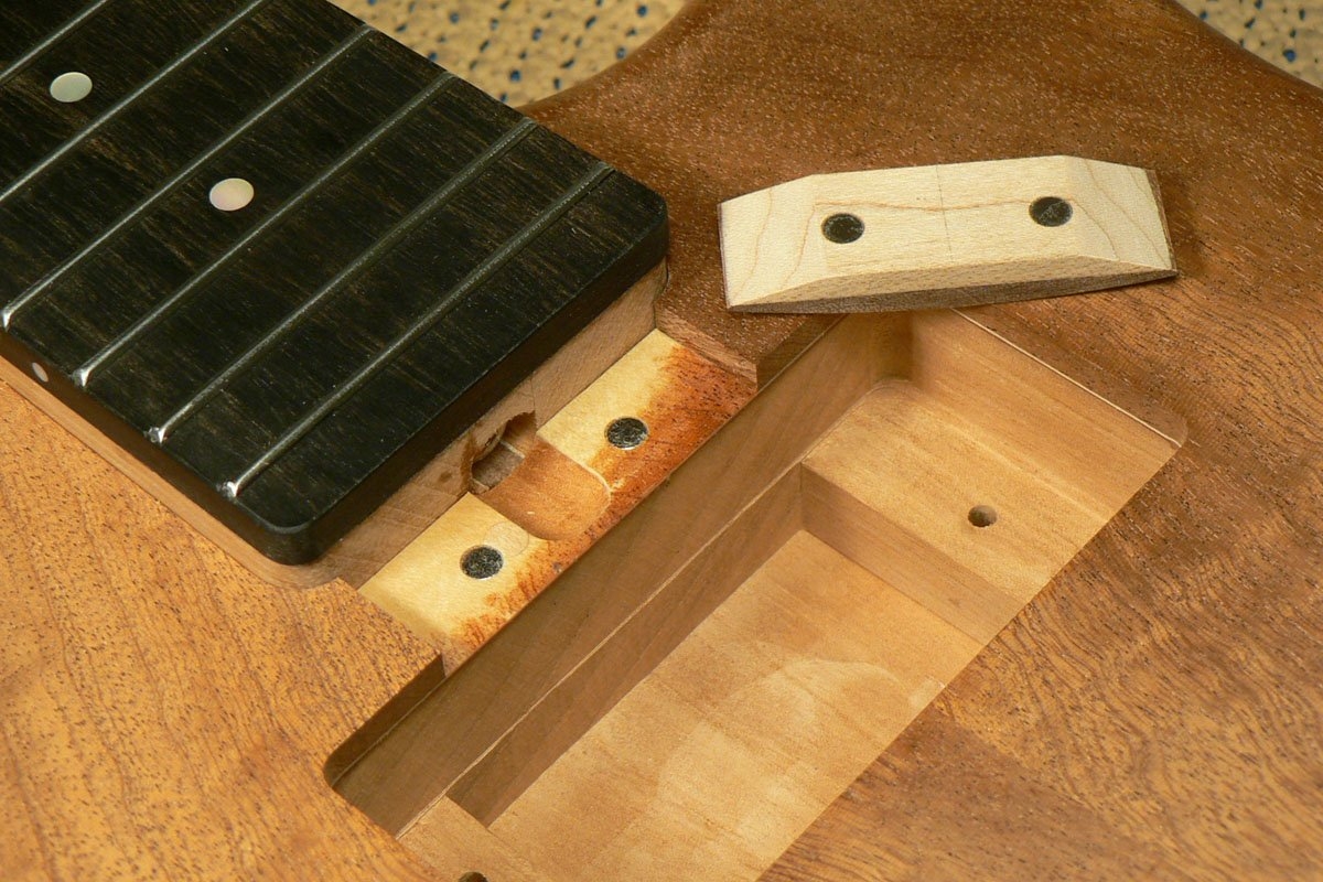
The magnets in the cover plate are slightly further away from the neck than the ones in the body, so the cover is pulled into contact with the neck. (Unless I put it in the wrong way round of course).
Here it is in place. . .
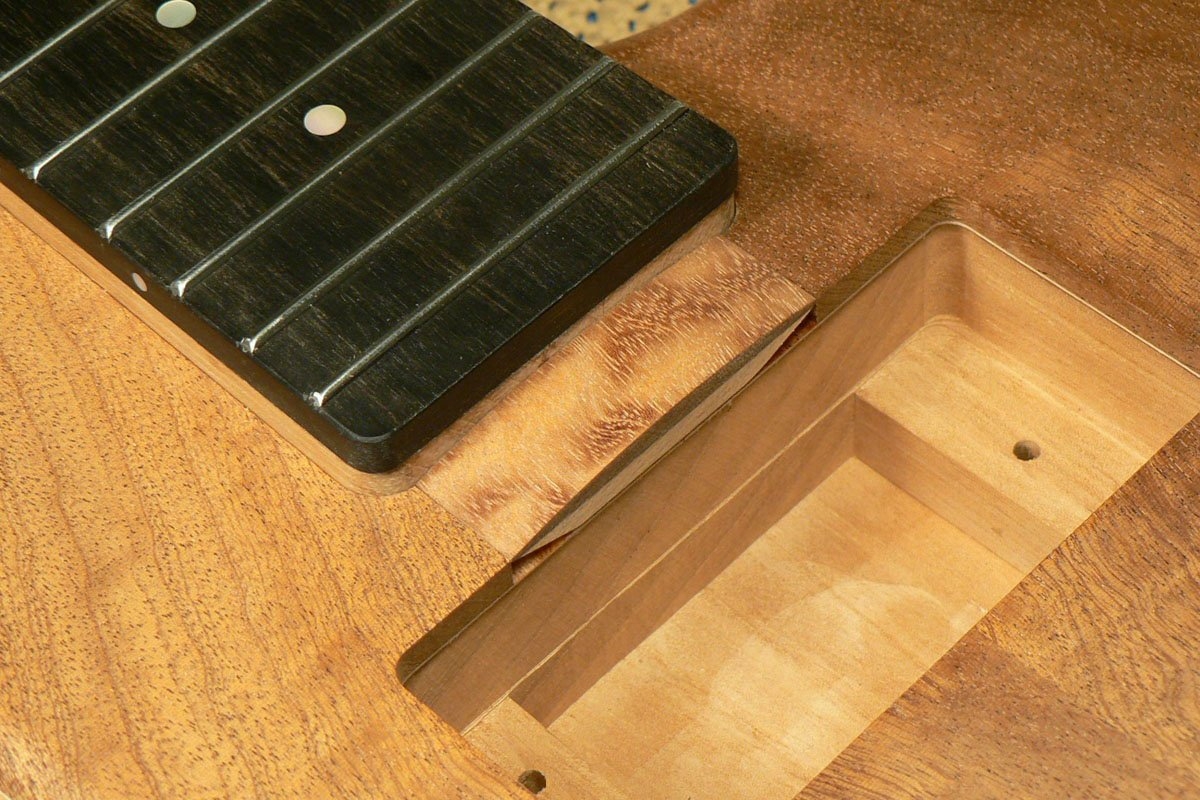
. . . and here’s how to get it out. . .
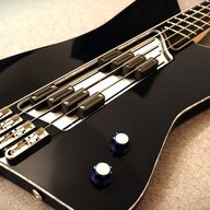
. . . and this is what it will look like when the pickups are installed.
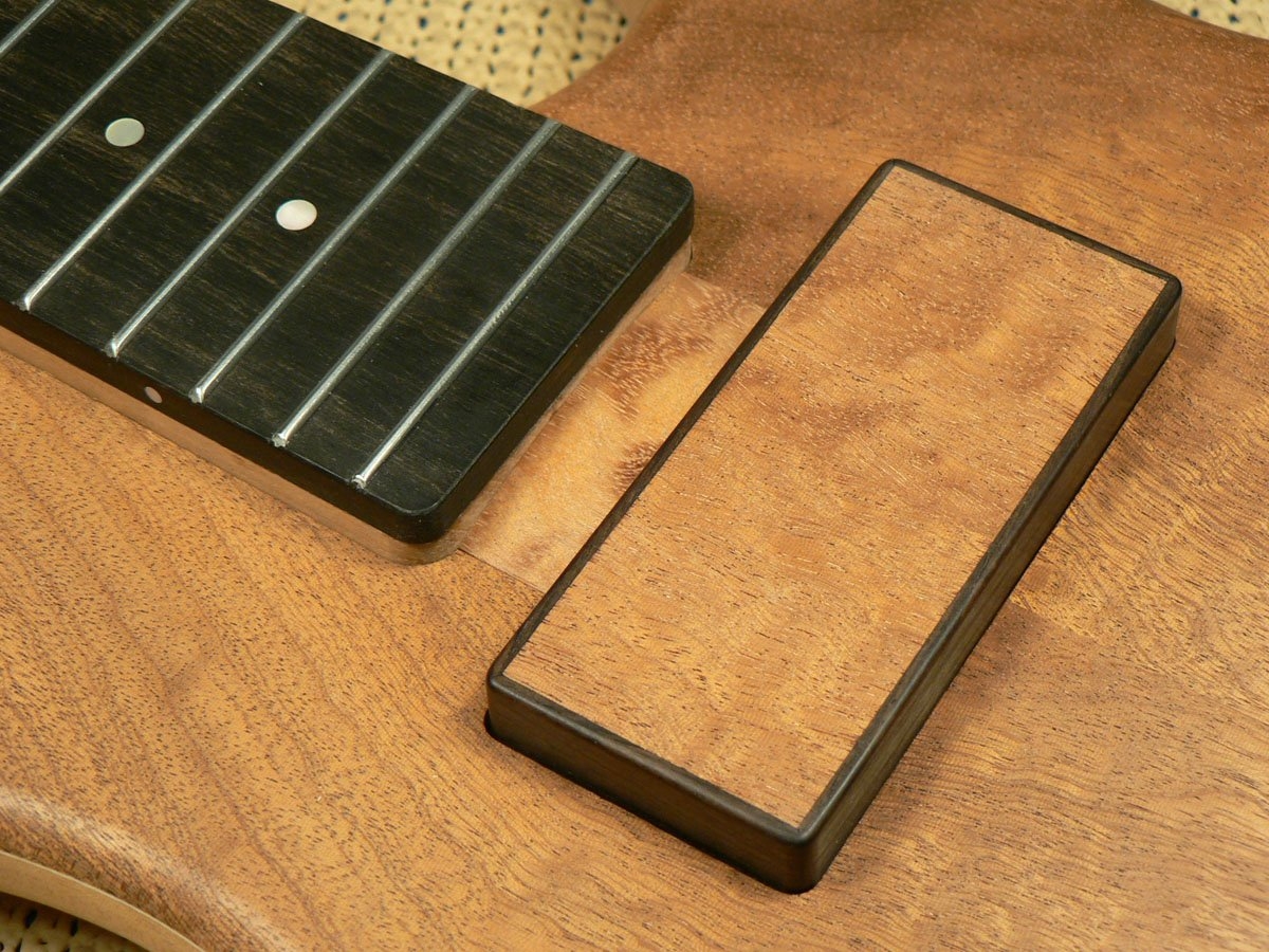
As I’ve mentioned in another thread, I didn’t want to recess the bridge/tuners into the body or angle the neck, so the neck protrudes more than ‘usual’ out of the body. This means that if the truss rod cover plate is flush with the body it doesn’t quite cover the truss rod hole. So I made a convex cover plate and rigged up this makeshift jig to sand a curve onto the top of it.
The magnets in the cover plate are slightly further away from the neck than the ones in the body, so the cover is pulled into contact with the neck. (Unless I put it in the wrong way round of course).
Here it is in place. . .
. . . and here’s how to get it out. . .
. . . and this is what it will look like when the pickups are installed.


