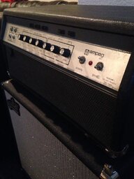
Yes I would advise resetting the bias if the 12AU7s are replaced. AFAIK the 12AX7 should have not impact on bias. Only the second section of each driver tube should be involved in bias.
The 50th AV webpage lists the small signal tubes in the power amp as one 12AX7 and two 12AU7s. The webpage calls all of them drivers tubes, but I don't think this is correct. I have not seen a schematic for the 50th AV, but I believe it is essentially a lightly modded SVT VR. In the VR, the 12AX7 is the phase inverter and the 12AU7s are driver tubes.
This image is from the VR schematic:
View attachment 4737276
I put red circles around the bias controls. One side of the bias controls are tied to -150V and the other side is tied to ground (OV). The bias controls determine the voltage passing along the red paths to the grids of the J3B and J5B. Notice that capacitors block this voltage from traveling back through the circuit to J3A or J5A. The voltage from each bias control sets the operating point of the J3B and J5B. Making the voltage more negative will reduce current in these tube stages (shown in green). Making the voltage less negative will increase current.
The cathode of these tube stages is also connected to -150V through a 47k resistor. The plates are connected to 305V. The bias (shown in orange) is essentially the voltage drop across the 47K resistors subtracted from the -150V supply. This voltage drop varies with current flow through the associated tube section.
Since the bias is approximately -48V and the supply is -150V, the voltage drop is +102V...(I.E. -150+102=-48V).
The current flow for this voltage drop is found with the formula I=V/R (I = 102V/47K=2.17mA)
So the bias controls are adjusted so J3B and J5B pass approximately 2.17ma at idle.