• TalkBass has been independent since 1998. Add your voice.
    Create a free account to reply to discussions, view embedded media, and browse with fewer display ads.
    Join freeLog in
    Want zero display ads or expanded classifieds tools? Compare plans.

Ampeg SVT-CL hums hums hums...

Looks like. Goes to "v1" = the driver tube?View attachment 3665997

Since your amp has the balanced out transformer, I suggest using the attached schematic (see page 2) for this part of the circuit. I can't think of any conceivable reason why the transformer would cause R14 to blow. Pretty sure the J10 header that connects at the junction of R14 and R13 is for the global feedback loop that comes from the secondary of the OT.
 

Attachments

  • Like
Reactions: agedhorse
Thank you guys.
I am still smoking the R14. I have replaced the driver tube along with 12AU7s too. The same thing. It does not blow any of the fuses, it does not go to the protection mode too.

What I remember of firing it for the first time 2 days ago - I forgot to connect two things: the gray ribbon (going from the right side of mainboard to the preamp) and the nearby 2-pin red stripe that goes to the speaker board. I was getting RED bias lights and no sound. So I looked over, found these two, hooked it up, fired, and it smoked the R14 then (along with the huge noise). No change since that time. It also does not matter what bias is set. Now it's fully counter clockwise.

When I hit power, then after few seconds flip standby (yes I know it's "Cold"), then I have those few seconds of warming up and after that both RED and GREEN bias lights up, and horrible noise is heard (you can see driver tube lights way more when the squelling noises appear). Then see the smoke of blown R14... Nothing looks suspect to me. I have checked all nearby resistors, diodes and caps. PCB traces looks OK. Power tube board also OK. Any other ideas?
 
Zdjęcie 14.01.2020, 10 38 46.jpgZdjęcie 14.01.2020, 10 38 48.jpgZdjęcie 14.01.2020, 11 43 23.jpg
 

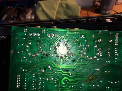
I don't like the look of this solder joint circled in red. It should be cleaned and reflowed, add a little flux when soldering. In general, there are a number of blobby solder joints that I don't like to see. Two big blobs next to each other could have a short. Sometimes, a joint can look fine but the lead can be loose and can be pulled right out if you give it a tug.

Check for any foreign material present between the bottom of the tube socket and the top of the PCB. Something can get jammed in there and cause a short. I use a pipe cleaner soaked in isopropyl alcohol (IPA, available from a pharmacy).

The solder side of the board should be cleaned with IPA to remove all the flux residue. A clean board helps you to find solder bridges when inspecting.

Check is anything from the chassis is shorting against the bottom of the board when installed. Check the standoffs.

3.jpg
 
Thank you guys.
I am still smoking the R14. I have replaced the driver tube along with 12AU7s too. The same thing. It does not blow any of the fuses, it does not go to the protection mode too.

What I remember of firing it for the first time 2 days ago - I forgot to connect two things: the gray ribbon (going from the right side of mainboard to the preamp) and the nearby 2-pin red stripe that goes to the speaker board. I was getting RED bias lights and no sound. So I looked over, found these two, hooked it up, fired, and it smoked the R14 then (along with the huge noise). No change since that time. It also does not matter what bias is set. Now it's fully counter clockwise.

When I hit power, then after few seconds flip standby (yes I know it's "Cold"), then I have those few seconds of warming up and after that both RED and GREEN bias lights up, and horrible noise is heard (you can see driver tube lights way more when the squelling noises appear). Then see the smoke of blown R14... Nothing looks suspect to me. I have checked all nearby resistors, diodes and caps. PCB traces looks OK. Power tube board also OK. Any other ideas?



Have you tried a different tube in V1? V1 is not the driver so it's not clear. FYI, V1a provides a bit of gain and V1b is the phase inverter. The V2 and V3 are the driver tubes.

What happens when V1 is totally out of the circuit? Usually when this sort of problem occurs I pull the tube and check the working voltages.

Measure the voltage on pin 2 with no tube in the socket. It should 0V. If you have positive voltage you have a bad couple cap on the cathode of the last tube in the preamp. Per the schematic this could put up to 100V on the control grid of V1, which would cause the massive current you are getting.

You can't really check the bias until you get the squealing under control. Hopefully with V1 out of the circuit the bias settles and can be set in the proper range.
 
  • Like
Reactions: boroman
You're completely right, I was reffering to V1 (wrongly as a "drivers").
I reflew some solder joints (all look OK, it looks way better in real that in the photo...)

I have no AC/DC voltage on PIN2 of V1 (or something less than 0,1V). Measured with power tubes off and V2+V3 in place. Also no shorts in the tube socket. But PIN 3 or PIN4.. damn I forgot to write it down which one was that!! has like 540V DC what made me think if that's OK?

Anyway I started to check the voltages on the power tubes and when I inserted DMM to PIN2 or PIN3 (to ground) of the first measured power tube socket, I smoked the R34 47k... What's going on here!?
 
Remove the tubes. 540VDC on a small signal tube is a big problem, something is miswired. Go back to the power supply nodes and check the DC references on the schematic. Check all jumpers. Make sure that nothing is in backwards. Trace this back to the small signal tubes.
In looking at the resistors when tracing the circuit, do not just read the color codes, measure with an ohm meter.
 
Yes, I measure them via DMM always rather than checking color coding.
By they way. I'm thinking... The gray ribbon (going to the preamp) and the two-wire red conenctor (to the spkr board) on the right side - they can be connected backwards. I don't remember how they were wired here, but I rely on two pics I have (one in the attachment, not mine) - and I connect it that way with the ribbon going towards bottom chassis - maybe it should be backwards?

For the red I think it does not matter at all (?)

pwr_chassis_inv.jpg
 

Attachments

  • Zdjęcie 15.01.2020, 15 44 51.png
    Zdjęcie 15.01.2020, 15 44 51.png
    4.2 MB · Views: 75
  • Zdjęcie 15.01.2020, 15 44 56.png
    Zdjęcie 15.01.2020, 15 44 56.png
    3.8 MB · Views: 69
And the story continues... after replacing 47k resistor and put back together I can't go to the "playing mode" (red light on the front). With tubes or without. No voltage passing to the preamp section (cold tubes), reading from schematic the PIN-5 of J4 should be carrying 345VDC to the preamp - and it's not here... . What a nightmare!
 
Last edited:
And the story continues... after replacing 47k resistor and put back together I can't go to the "playing mode" (red light on the front). With tubes or without. No voltage passing to the preamp section (cold tubes), reading from schematic the PIN-5 of J4 should be carrying 345VDC to the preamp - and it's not here... . What a nightmare!

I can definitely appreciate your tenacity, but way before now, I would have packed the unit up and shipped it to the Ampeg factory service center, much easier said than done, I fully realize.

It appears that the further you go in the amp, the worse things get. Not at all assigning blame for that anywhere in particular.

You’ve certainly made the all-star efforts at repairing the amp.

Good luck either way you go.
 
  • Like
Reactions: agedhorse
And the story continues... after replacing 47k resistor and put back together I can't go to the "playing mode" (red light on the front). With tubes or without. No voltage passing to the preamp section (cold tubes), reading from schematic the PIN-5 of J4 should be carrying 345VDC to the preamp - and it's not here... . What a nightmare!

You have to break the problem down into simpler sections. Deal with one issue at a time. Trace the power supply voltages one step at a time from the rectifier and smoothing capacitors through to the preamp. Do this without the tubes plugged in.
 
With the last two weeks I've been trying to power it on - no success.
I have recapped whole power section to be sure it's not there.
All the resistors OK. I don't see any problems in the mainboard (I looked over it hundreds of times...)

The front light stays red.

Does not go to green when I hit standby, does not flash. Just nothing happens when I hit "standby". The two 12AX7 preamp tubes are not glowing. The same with two different CL preamps (with different tubes). The J4 connection cable is OK. What could be next? The gray ribbon?
 
Looking at an amp isn't going to help, you can't see most defects. If you measured the supply voltages and ripple voltage, you would have realized that the caps were not the issue.

You need to do REAL troubleshooting. Do you understand how the circuit is supposed to work?

At this point, a qualified and conscious tech will need to charge more because he should go over everything you touched looking for additional mistakes that may have been introduced.
 
With the last two weeks I've been trying to power it on - no success.
I have recapped whole power section to be sure it's not there.
All the resistors OK. I don't see any problems in the mainboard (I looked over it hundreds of times...)

The front light stays red.

Does not go to green when I hit standby, does not flash. Just nothing happens when I hit "standby". The two 12AX7 preamp tubes are not glowing. The same with two different CL preamps (with different tubes). The J4 connection cable is OK. What could be next? The gray ribbon?

You have to measure all the voltages both at the power supply source and at the destination tubes. You should be able to trace the 12AX7 heater voltages to pinpoint where the issue is. Do that for the high voltages as well. Measure at each end of the gray connector's terminals where they are soldered to the board. Not only do the voltages have to be there but they have to be correct as per the schematic.
 

Latest posts